
Reaction sputtering system

A sputtering system and reaction technology, applied in the field of reactive sputtering systems, can solve the problems of impure thin film composition, difficult to obtain thin film, inaccurate control of reactive gas partial pressure, etc., and achieve the effect of improving stability and repeatability

Inactive Publication Date: 2010-10-20
北方广微科技有限公司
View PDF0 Cites 9 Cited by
  • Summary
  • Abstract
  • Description
  • Claims
  • Application Information

AI Technical Summary

Problems solved by technology

To get VO 2 The oxygen content must be strictly controlled during the film preparation process, and it is difficult to precisely control the flow of oxygen in the traditional reactive sputtering system, s

Method used


Image

  • Reaction sputtering system
  • Reaction sputtering system
  • Reaction sputtering system

Examples


Example

[0022] Comparative test example

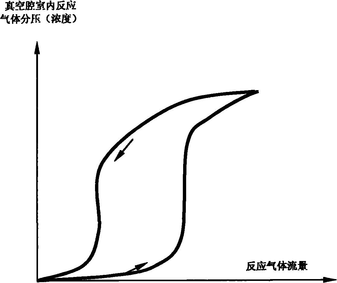
[0023] When sputtering thin films using Varian 2000 / 8 vacuum sputtering system, take the sputtering power of DC900W as an example. When the oxygen flow rate is lower than the critical point of 5.5SCCM, the sputtered film composition is mainly VO, and the film volume The resistivity is about 0.001Ω·cm. When the oxygen flow rate exceeds the critical point of 5.5 SCCM, the sputtering current drops sharply, and the final volume resistivity of the sputtered film is greater than 1000Ω·cm, and the main component is V 2 O 5 . It cannot sputter the +4 vanadium oxide VO 2 .

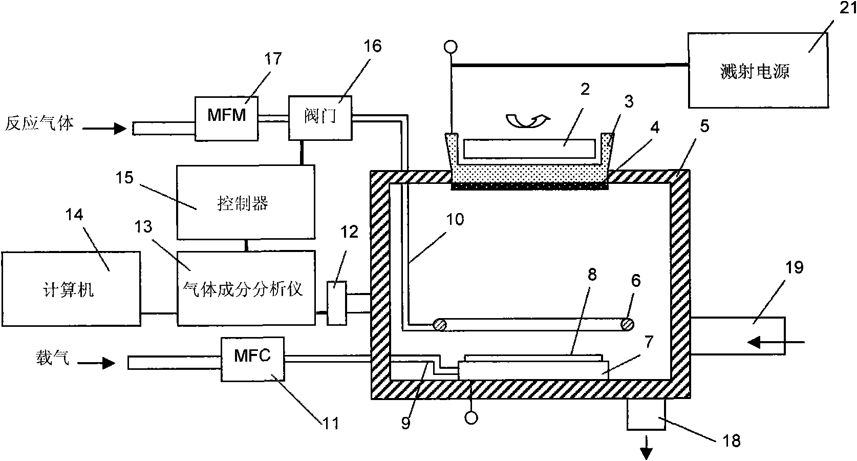
[0024] According to the present invention, the 2000 / 8 model vacuum sputtering system is modified to add the gas control system of the present invention. That is to add a ring to improve the distribution of the reaction gas on the top of the wafer stage in the vacuum chamber 5; add a residual gas detection system HPQ-2 manufactured by MKS company (its function is equivalent to the pres...


PUM


Abstract

The invention provides a reaction sputtering system which comprises a vacuum cavity, a reaction gas pipeline, a gas-carrier pipeline and a gas control system. The reaction gas pipeline, the gas-carrier pipeline and the gas control system are connected with the vacuum cavity, a valve the opening of which is controlled by an electric signal is arranged on the reaction gas pipeline; the gas control system comprises a gas content analysis instrument, a computer and a controller which are all communicated with the vacuum cavity through pipelines, the gas content analysis instrument is used for measuring a partial pressure value of a reactive gas under the control of the computer and further converting the partial pressure value into an electric signal value proportional to the partial pressure value, and an electric signal value corresponding to a standard partial pressure value of the reactive gas is set in the controller and combined with the electric signal value received from the gas content analysis instrument to calculate the offset of the electric signal value and adjust the value opening according to a calculation result so that the partial pressure value of the reactive gas in the vacuum cavity is kept on a set value level. By using the system of the invention, the stability and the repeatability of the sputtering process can be greatly improved, and a metal compound film which can not be prepared by using traditional equipment can be sputtered.

Description

technical field [0001] The invention relates to a reactive sputtering system for preparing semiconductor thin films. Background technique [0002] The structure of a traditional reactive sputtering system includes: a vacuum chamber, a sputtering power supply, a vacuum system connected to the vacuum chamber, a wafer transfer system and a gas control system. Wherein, a wafer carrier is provided at the center of the bottom of the vacuum chamber, and a wafer to be sputtered equivalent to an anode is placed on the wafer carrier. A target device is arranged on the top of the vacuum chamber, and the target device includes a base for placing the target, a cathode target connected to the base, and a rotating strong magnet array. The sputtering process is carried out in a certain vacuum environment. When a certain amount of argon gas is introduced into the vacuum chamber and a voltage is applied between the cathode and the anode, a gas self-excited discharge will occur. The cathode ...

Claims


Application Information

Patent Timeline
IPC IPC(8): C23C14/34C23C14/54
Inventor 郭俊雷述宇
Owner 北方广微科技有限公司
Learn More