
Pulse clarification tank

A clarifier and pulse technology, applied in sedimentation tanks, chemical instruments and methods, separation methods, etc., can solve the problems of small rising flow rate of clean water, large tank area, low sludge concentration, etc., to improve hydraulic load and simple maintenance. , the effect of reducing land occupation

Inactive Publication Date: 2010-10-20
SUEZ WATER TREATMENT CO LTD
View PDF3 Cites 8 Cited by
  • Summary
  • Abstract
  • Description
  • Claims
  • Application Information

AI Technical Summary

Problems solved by technology

[0003] The invention solves the technical deficiencies of the existing clarification tanks, such as relatively small rising velocity of clear water, large tank area, large land occupation, and low sludge concentration; High, small footprint, pulse clarifier with good effluent quality

Method used


Image

  • Pulse clarification tank
  • Pulse clarification tank
  • Pulse clarification tank

Examples


Embodiment Construction

[0020] The present invention will be described in further detail below in conjunction with the accompanying drawings and embodiments.

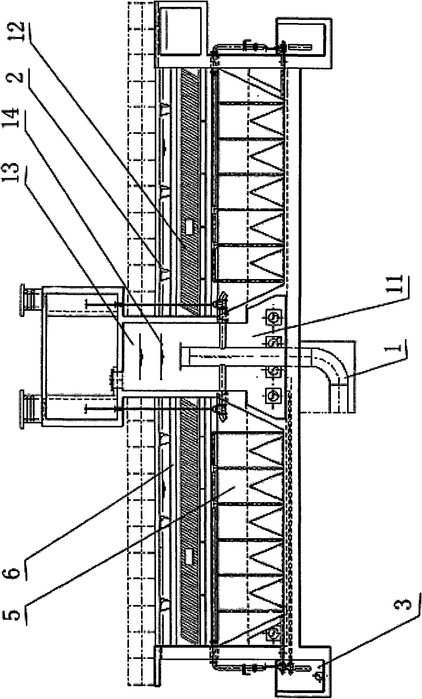
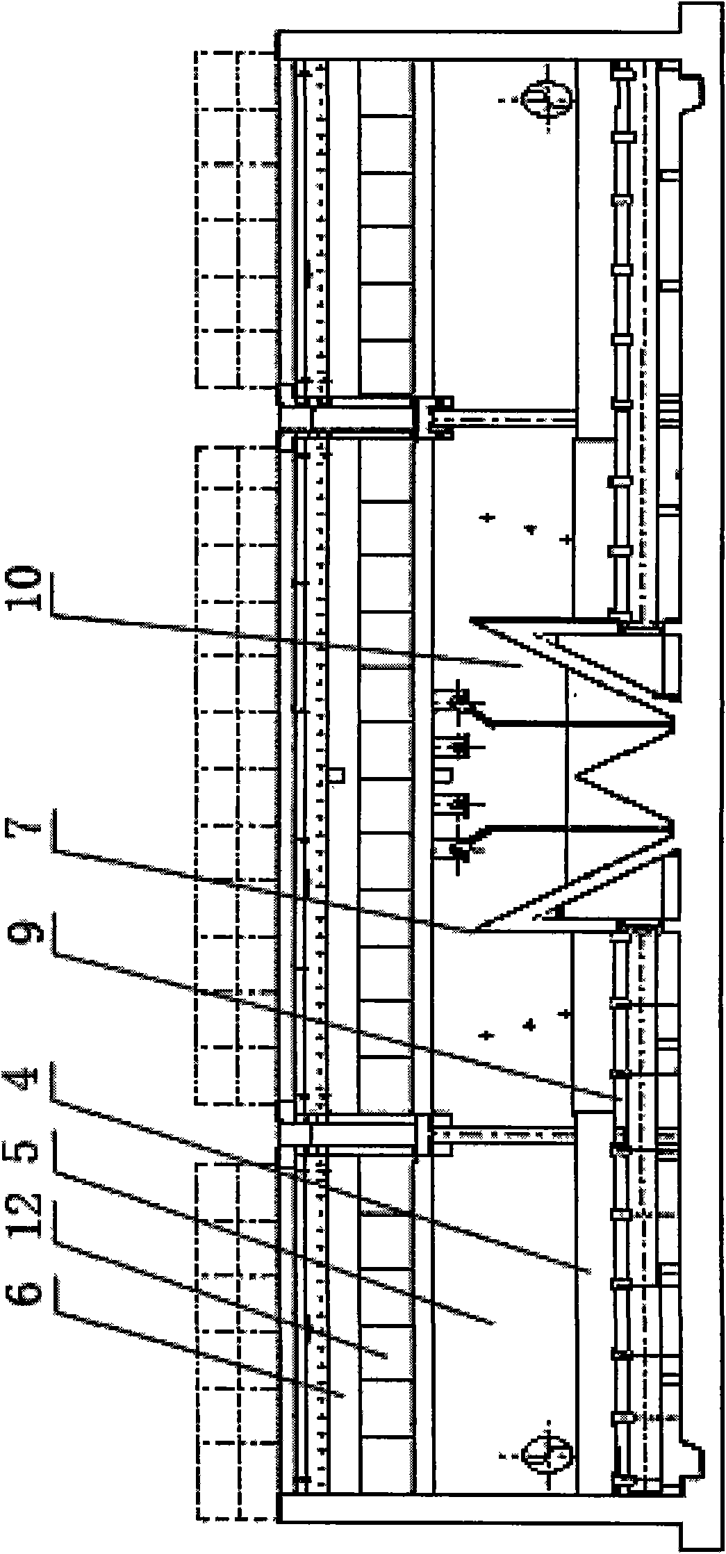
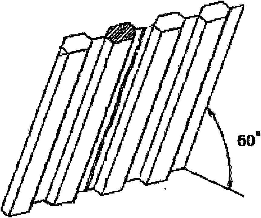
[0021] Such as Figure 1-Figure 3 As shown, the present invention includes a pulse generator made up of a raw water inlet pipe 1, a water inlet chamber, a blower, and a vacuum breaking valve, and a raw water distribution pipe 9, a clarified water collection tank 2, a mud discharge ditch 3, a rectifying plate 4, and a clarifying The pool body composed of the pool and the sludge thickening chamber 10. The clarifiers are arranged in square, circular or rectangular shapes. The water inlet chamber is divided into an upper vacuum chamber 13 and a raw water distribution chamber 11 at the bottom. The top of the water inlet chamber is provided with a vacuum breaking valve (electric or pneumatic), and the top of the vacuum chamber 13 is provided with a blower connected to the outside atmosphere. The water inlet chamber is provided with a liquid level...


PUM


Abstract

The invention discloses a pulse clarification tank, which comprises a pulse generator and a tank body, wherein the pulse generator consists of a raw water inlet pipe, a water inlet chamber, a blast blower and a vacuum damage valve, the tank body consists of a raw water distribution pipe, a clarified water collection groove, a mud discharge channel, a rectification plate, a clarification tank and a mud concentration chamber, wherein the vacuum chamber of the upper part of the water inlet camber is connected with the blast blower and the vacuum damage valve, a raw water distribution chamber at the lower part of the water inlet chamber is connected with the raw water inlet pipe, the raw water distribution chamber is connected with the bottom of the clarification tank, a clear water layer arranged at the upper part and a mud layer arranged at the bottom are arranged in the clarification tank, the upper part of the clear water layer is provided with a clear water collection tank, a layer of inclined pipes are arranged between the mud layer and the clear water layer, and the inclined pipes are densely distributed between the clear water layer and the mud layer, and mud concentration chambers is arranged. The invention has the advantages of large surface water power load, good flocculation effect, high mud concentration, ground occupation reduction and good water quality of outlet water.

Description

technical field [0001] The invention belongs to the field of water supply and sewage treatment, and relates to a water supply purification and clarification tank, in particular to a pulse clarification tank. Background technique [0002] At present, with the process of national industrialization and urbanization, the discharge of industrial and domestic sewage has increased significantly, and the treatment of sewage has become an urgent problem to be solved for sustainable development. The clarification tank is a feed water treatment system that utilizes the sludge accumulated in the tank to contact and adsorb the impurity particles in the raw water to achieve a faster separation from the clean water. This system can fully exert the role of the coagulant and improve the clarification efficiency. The clarifier is generally divided into sludge circulation (reflux) and sludge suspension (filtration) according to the sludge condition. Among them, the pulse clarifier belongs to ...

Claims


Application Information

Patent Timeline
Patent Type & Authority Applications(China)
IPC IPC(8): B01D21/02B01D21/28
Inventor 裴瀚笛陆子维
Owner SUEZ WATER TREATMENT CO LTD
Learn More