Cycloid rotor engine

A rotor engine and rotor technology, which is applied to combustion engines, machines/engines, internal combustion piston engines, etc., can solve the problems of difficult processing, low energy conversion efficiency of engines, and reduced power of the whole machine, and achieve easy production, processing and installation, and low energy consumption. The effect of high conversion efficiency and precise ignition timing

Inactive Publication Date: 2010-10-06
谢坤
View PDF5 Cites 5 Cited by
  • Summary
  • Abstract
  • Description
  • Claims
  • Application Information

AI Technical Summary

Problems solved by technology

1. The engine uses the reciprocating motion of the piston for energy conversion, so the limit speed of the engine is low, and the energy lasts for 180 degrees when the crankshaft rotates 360 degrees
2. All reciprocating engines are equipped with a ventilation valve mechanism, which not only increases the volume of the whole machine, but also increases the weight of the whole machine
3. The reciprocating engine uses the crankshaft and connecting rod for power output. When the piston is close to the top dead center and the bottom dead center, the effective arm of this output is very small, so that the expansion force in the cylinder cannot be fully exerted, and the energy conversion rate very low
4. When the reciprocating engine is ignited, the ignition timing needs to be very precise, otherwise it is easy to be too early or too late, resulting in a reduction in the power of the whole machine
1. The rotor in the triangular rotor engine rotates eccentrically during the working process, so there will be a lot of vibration when the engine is working
2. The cylinder shape of the triangular rotor engine is crescent-shaped, which is composed of a triangular rotor and an elliptical outer wall. This shape is not conducive to the combustion of gas
3. The compression ratio of the rotary engine is small, and compression ignition power cannot be used
4. The sealing of the triangular rotor engine is difficult and the processing is not easy
5. When the engine is working, the pressure of the expanded gas in the cylinder is decomposed, and the effective torque is very small, so that the energy conversion efficiency of the engine is lower than that of the reciprocating engine. , so general heavy equipment or off-road vehicles cannot install this type of engine, only high-speed racing cars or aircraft can be used, making it difficult to promote

Method used


Image

  • Cycloid rotor engine
  • Cycloid rotor engine
  • Cycloid rotor engine

Examples


Embodiment Construction

[0039] 1. Various components of a single rotor engine

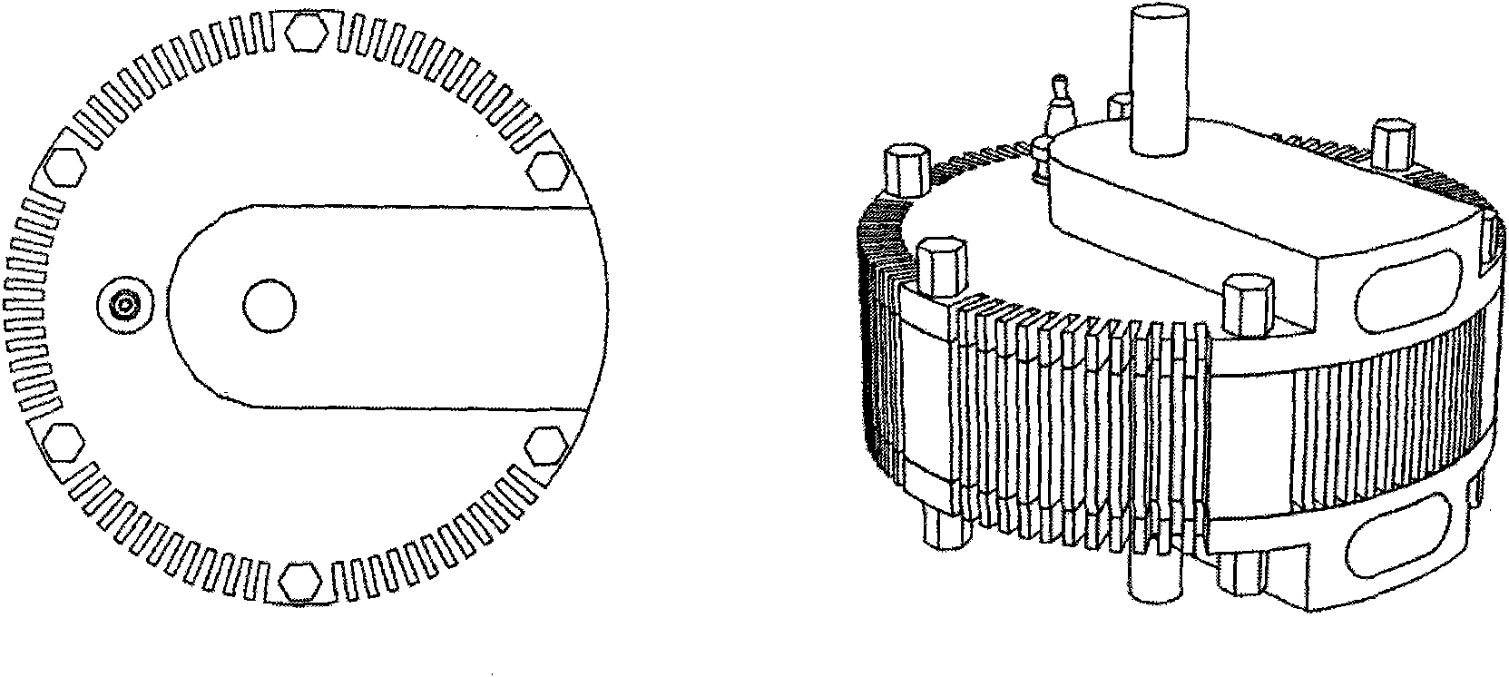
[0040] like figure 1 Shown is a schematic diagram of the appearance of the engine, from which it can be understood that the shape of the engine of the present invention is a cylinder, and the output shaft of the engine protrudes from the upper and lower top surfaces of the cylinder for connecting load equipment. And the position of the shaft hole protruding from the output shaft is not at the center point of the top surface of the cylinder, but to one side. On the left side of the output shaft, a spark plug is installed on the housing, and on the other side, a spark plug is installed on the upper and lower housings. One air port, one of which is the intake port and the other is the exhaust port. The three shell components of the whole machine are arranged side by side and fixed with a circle of bolts.

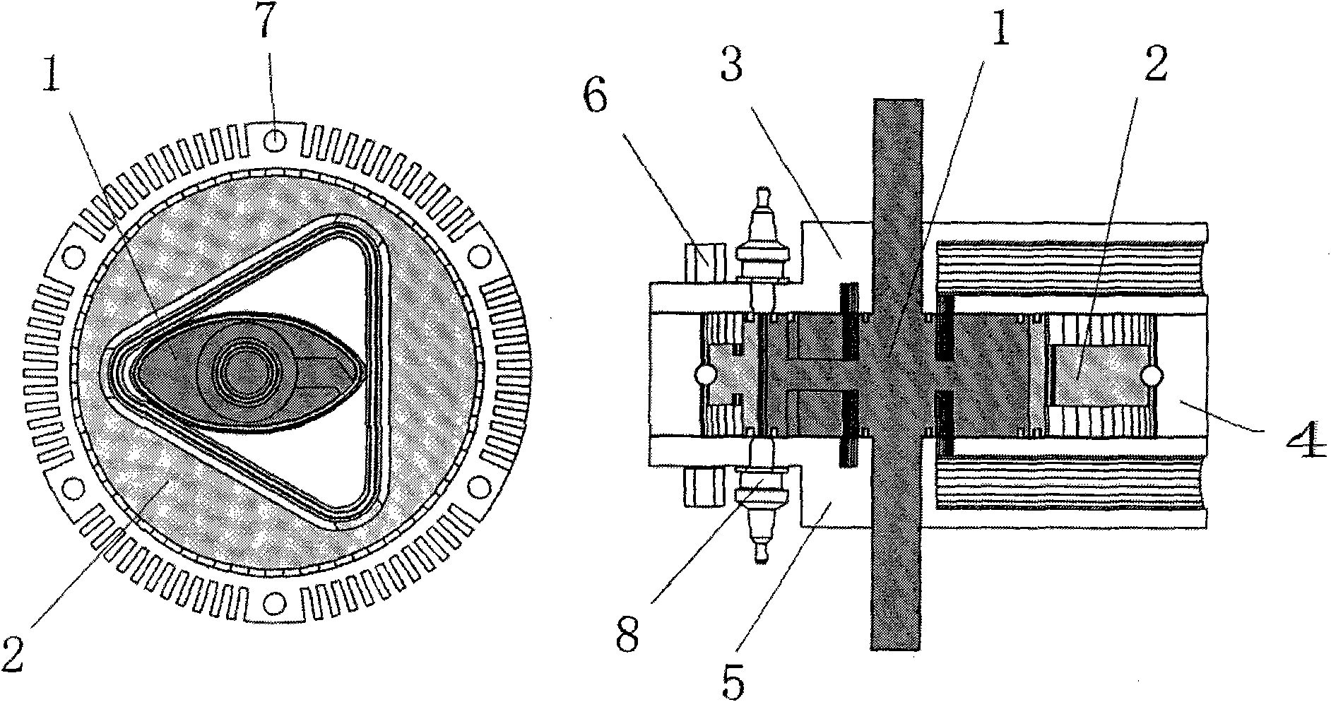
[0041] like figure 2The schematic diagrams of the cross-section and longitudinal section of the engine are shown. Al...


PUM


Abstract

The invention relates to a cycloid rotor engine, which consists of a plurality of casings arranged in parallel to form a stator assembly, and a cycloid mechanism arranged inside forms a rotor assembly. In the cycloid mechanism, an elliptic rotor is arranged in a round disc member with a triangular cavity, and when the elliptic rotor and the member with the triangular cavity rotate with the angular velocity of 3:2 by taking respective central point as the axis, capacities of three cylinders change periodically; and a rotor air channel as well as an upper casing and a lower casing form a ventilation channel, and ignition is realized by a casing spark plug or a thermal lag time coil on the rotor, thereby forming a four-stroke engine in continuous rotation without a linkage mechanism or a gear mechanism.

Description

a technical field [0001] The invention relates to a cycloidal rotor engine, in particular to a vibration-free, high-speed, high-torque, high-power engine composed of an elliptical rotor and a triangular cavity component rotating together. Two background technology [0002] Among the existing engines, the ones with more mature technology are mainly reciprocating piston engines and Wankel triangular rotor engines for vehicles. Among the above two types of engines, the reciprocating engine has been designed and improved for more than one hundred years, and there are several problems that cannot be changed. 1. The engine uses the reciprocating motion of the piston for energy conversion, so the limit speed of the engine is low, and the energy lasts for 180 degrees when the crankshaft rotates 360 degrees. 2. All reciprocating engines are provided with a ventilation valve mechanism, which not only increases the volume of the whole machine, but also increases the weight of the whol...

Claims


Application Information

Patent Timeline
IPC IPC(8): F02B53/02F02B55/02F02B53/04F02B55/16F02B53/12
CPCY02T10/17Y02T10/12
Inventor 尚世群
Owner 谢坤
Why Eureka
Try Eureka