
Voltage-reducing and electricity-saving controller of motor

A power-saving controller, motor technology, applied in AC motor control, motor generator/starter, starter of a single multi-phase induction motor, etc., can solve the problems of low accuracy, narrow power range, waste, etc., Achieve the effect of ensuring accuracy, large power range and improving accuracy

Inactive Publication Date: 2010-09-29
JIANGSU LEAP MACHINE
View PDF0 Cites 2 Cited by
  • Summary
  • Abstract
  • Description
  • Claims
  • Application Information

AI Technical Summary

Problems solved by technology

As far as our country is concerned, asynchronous motors are widely used in various electric drive systems, and the power consumption accounts for about 60%-70% of the total power consumption in the country, and usually 60% of the motors are at 60% or 60%. It is quite common for large horse-drawn carts or low-load operation, resulting in low operating efficiency and power factor of the motor
In this case, a considerable part of the electric energy consumed by the motor is wasted in the form of heat generation, iron loss, noise and vibration, resulting in a large waste of electric energy
[0003] At present, most motor controllers only solve the problem of soft start, that is, the problem of step-down start. The circuit of the existing energy-saving controller uses sampling circuit sampling to judge the operation of the motor, but the sampling is often a waveform. It also needs to be fed back after conversion and information processing. It cannot realize real-time detection of power factor angle and control of triggering of thyristor. Its accuracy is not high, and its power range is narrow, so it is not universal.

Method used


Image

  • Voltage-reducing and electricity-saving controller of motor
  • Voltage-reducing and electricity-saving controller of motor
  • Voltage-reducing and electricity-saving controller of motor

Examples


Embodiment Construction

[0023] The present invention will be described in further detail below in conjunction with the embodiments given in the accompanying drawings.

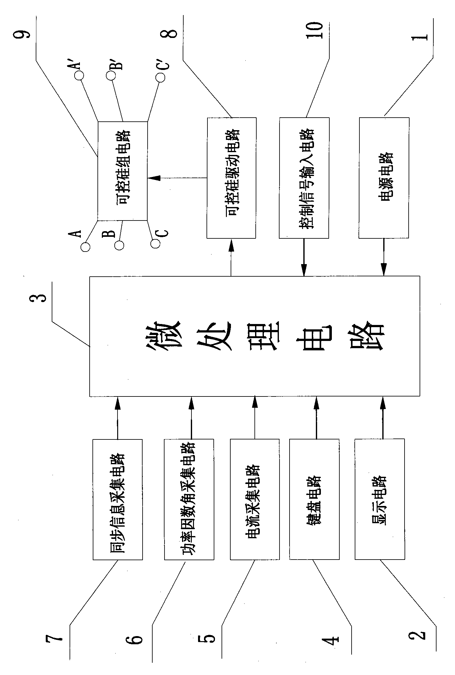
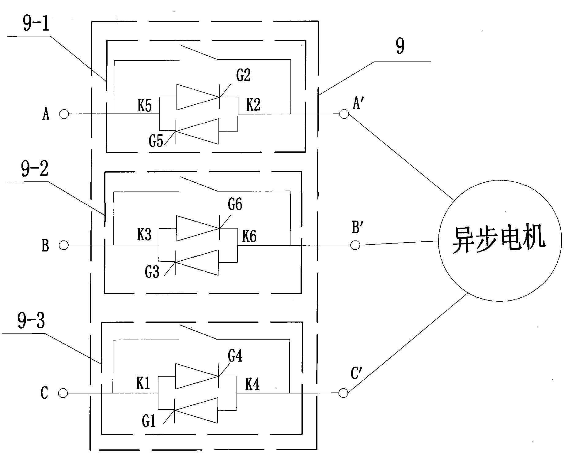
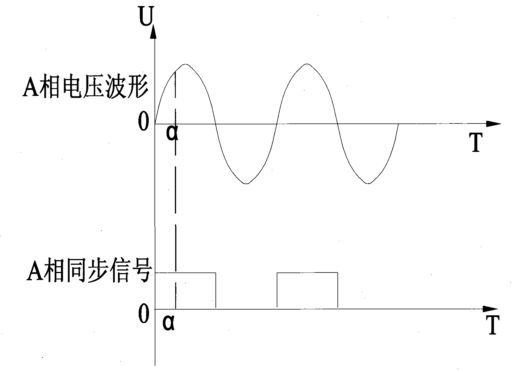
[0024] Such as figure 1 , 2 , 4, 5, 6, 7, and 8, a motor step-down power-saving controller, including a power supply circuit 1, a microprocessor circuit 3 and a power factor angle acquisition circuit 6, a power supply circuit 1, a power factor angle acquisition circuit 6 are all connected with the microprocessor circuit 3, and also include a current acquisition circuit 5, a synchronous information acquisition circuit 7, a thyristor drive circuit 8, a thyristor circuit 9 and a control signal input circuit 10, a current acquisition circuit 5, a synchronous information Acquisition circuit 7, thyristor drive circuit 8 and control signal input circuit 10 are respectively connected with microprocessor circuit 3, and described thyristor circuit 9 includes first thyristor group 9-1, second thyristor Group 9-2 and the third thyristor group 9...


PUM


Abstract

The invention discloses a voltage-reducing and electricity-saving controller of a motor, comprising a power supply circuit, a microprocessor circuit and a power factor angle acquisition circuit, wherein the power supply circuit is connected with the microprocessor circuit; the controller also comprises a current acquisition circuit, a synchronous information acquisition circuit, a silicon-controlled drive circuit, a silicon-controlled circuit and a control signal input circuit which are respectively connected with the microprocessor circuit, wherein the silicon-controlled circuit comprises a first silicon-controlled group, a second silicon-controlled group and a third silicon-controlled group; each silicon-controlled group comprises two pieces of one-way controlled silicon which are reversely connected in parallel; one end of each group of three silicon-controlled groups is the input end of the controller and the other end is the output end of the controller; and the silicon-controlled drive circuit comprises a first drive circuit, a second drive circuit and a third drive circuit which are connected with the trigger ends of the first, the second and the third silicon-controlled groups in sequence. The invention has the advantages of favorable real-time property, high accuracy and commonality.

Description

technical field [0001] The invention belongs to the technical field of motor energy saving, and in particular relates to a motor voltage-reducing and power-saving controller. Background technique [0002] With the rapid development of modern technology, asynchronous motor, as the most important power device, has been widely used in today's industrial production and daily life, and is the main consumer of electric energy. As far as our country is concerned, asynchronous motors are widely used in various electric drive systems, and the power consumption accounts for about 60%-70% of the total power consumption in the country, and usually 60% of the motors are at 60% or 60%. It is quite common for large horse-drawn carts or low-load operation, resulting in low operating efficiency and power factor of the motor. In this case, a considerable part of the electric energy consumed by the motor is wasted in the form of heat generation, iron loss, noise and vibration, resulting in a ...

Claims


Application Information

Patent Timeline
Patent Type & Authority Applications(China)
IPC IPC(8): H02P1/28H02P23/00
Inventor 蒋波张金波
Owner JIANGSU LEAP MACHINE
Learn More