
Crank shaft grinding method and crank shaft grinding machine

A crankshaft and grinding technology, which is applied in the direction of machine tools, grinding machines, grinding/polishing equipment designed for grinding the rotating surface of workpieces, etc., can solve the problem that the parallelism between the connecting rod journal and the main journal cannot be guaranteed, and the connecting rod journal is eccentric Problems such as low distance accuracy, low angle accuracy, and low grinding accuracy of connecting rod journals can achieve the effects of improved angle accuracy, high work efficiency, and improved grinding accuracy

Inactive Publication Date: 2010-09-22
北京诺思泰格精密技术有限公司
View PDF4 Cites 6 Cited by
  • Summary
  • Abstract
  • Description
  • Claims
  • Application Information

AI Technical Summary

Problems solved by technology

During the indexing process of the fixture, there are installation errors and indexing errors, which make the eccentricity accuracy of the connecting rod journals and the angle accuracy between each connecting rod journals low, which in turn makes the grinding accuracy of the connecting rod journals lower
[0007] In addition, in the machining process of a crankshaft, after grinding one connecting rod journal, before grinding another connecting rod journal, the connecting rod journal needs to be indexed, and the main journal also needs to be The crankshaft is indexed so that the main journal can be cylindrically ground. A crankshaft needs multiple grinding processes to complete, and the work efficiency is low, and the parallel accuracy of the connecting rod journal and the main journal cannot be guaranteed

Method used

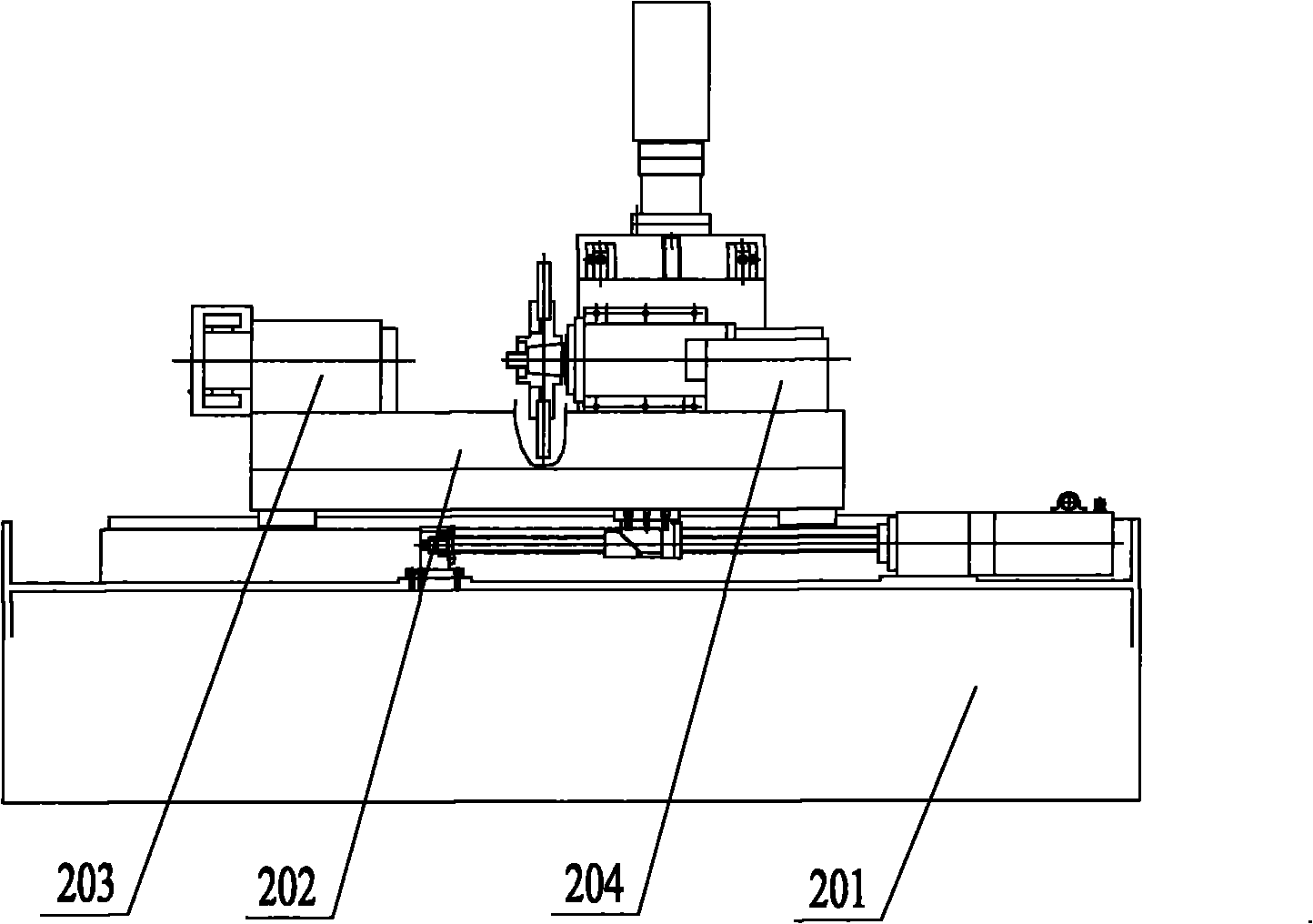
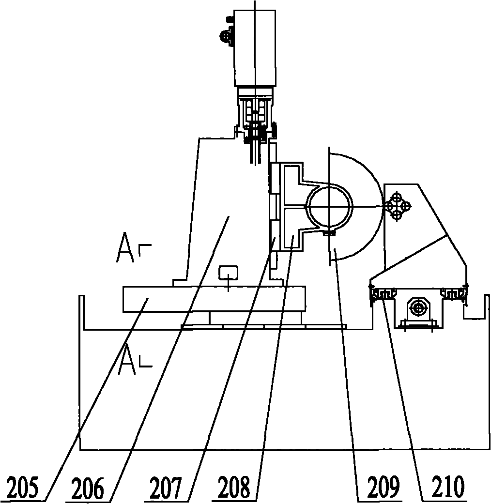

Image

  • Crank shaft grinding method and crank shaft grinding machine
  • Crank shaft grinding method and crank shaft grinding machine
  • Crank shaft grinding method and crank shaft grinding machine

Examples


Embodiment Construction

[0030] The first core of the present invention is to provide a crankshaft grinding method. When the crankshaft grinding method grinds the connecting rod journal of the crankshaft, the connecting rod journal can rotate at a uniform speed, and the grinding accuracy of the connecting rod journal is relatively high. high. Another core of the present invention is to provide a crankshaft grinding machine tool.

[0031] In order to enable those skilled in the art to better understand the technical solutions of the present invention, the present invention will be further described in detail below in conjunction with the accompanying drawings and specific embodiments.

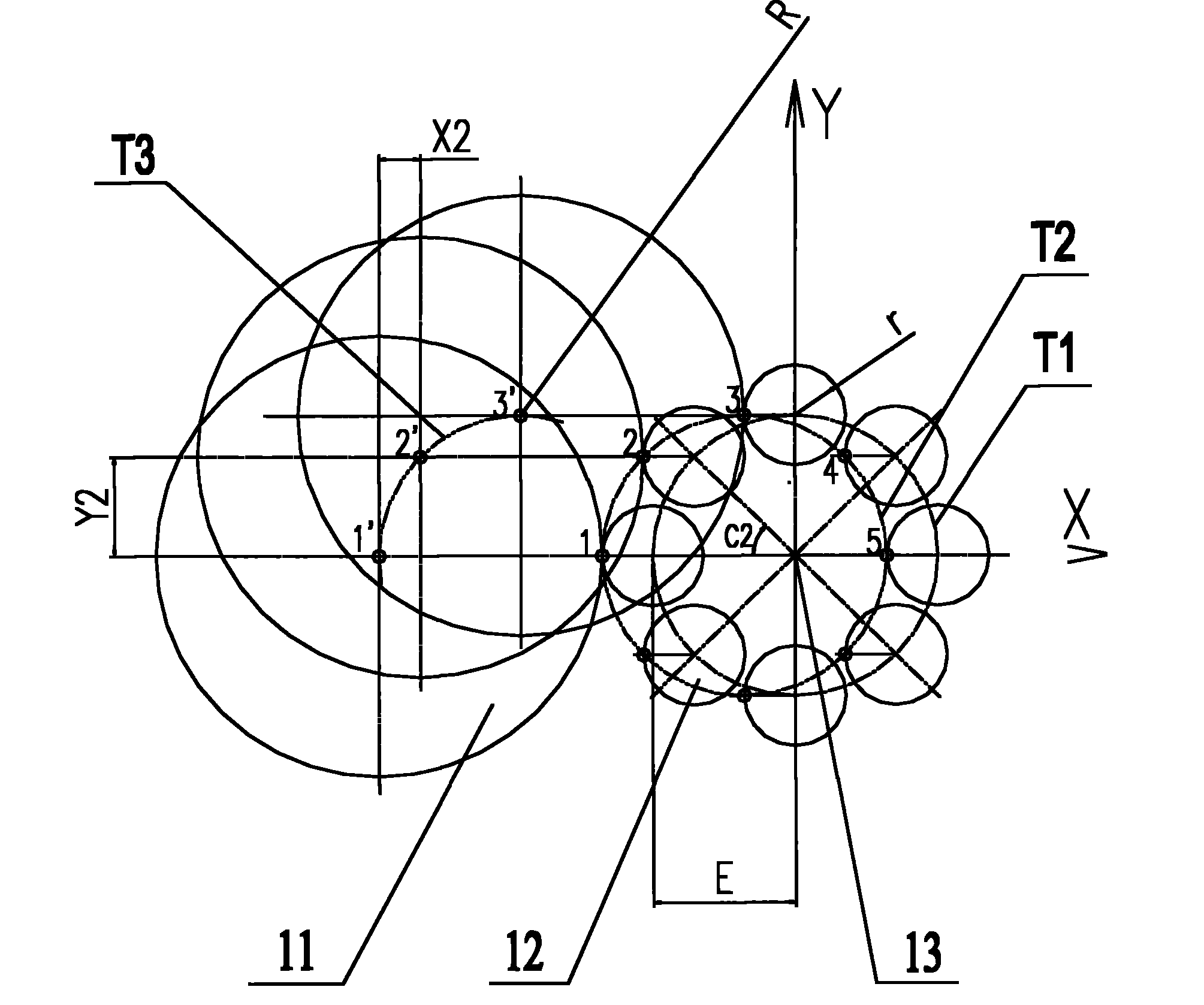
[0032] Please see figure 1 , figure 1 It is a schematic diagram of the principle of the crankshaft grinding method provided by the present invention.

[0033] like figure 1 As shown, the main journal of the crankshaft is connected with the driving device. The central axis of the main journal of the crankshaft is the...


PUM


Abstract

The invention relates to the technical field of machining, and discloses a crank shaft grinding method. The crank shaft grinding method comprises the following steps that: a crank shaft rotates around the rotation centre of the crank shaft; and the rotation centre of a grinding wheel moves according to a predetermined movement track curve, so that the high point of the grinding wheel grinds the high point of a connecting rod journal all the time. Only by making the rotation centre of the grinding wheel move according to the predetermined movement track curve, the crank shaft grinding method can ensure that the high point of the grinding wheel tracks and grinds the high point of the connecting rod journal all the time so as to grind the connecting rod journal and ensure high grinding accuracy of the connecting rod journal. The invention also discloses a crank shaft grinding machine.

Description

technical field [0001] The invention relates to the technical field of mechanical processing, in particular to a crankshaft grinding method. The present invention also relates to a crankshaft grinding machine tool for grinding a crankshaft by using the crankshaft grinding method. Background technique [0002] The crankshaft is the main rotating part of the engine. The crankshaft has two main parts: the main journal and the connecting rod journal. The central axis of the main journal is the rotation center of the crankshaft, and the connecting rod journal has a certain eccentric distance from the rotation center. When the crankshaft rotates around its own rotation center, the connecting rod journal revolves around the rotation center. [0003] After the crankshaft is formed, in order to make the size of the crankshaft meet a certain accuracy requirement, the crankshaft needs to be ground. The grinding process of the crankshaft is mainly to grind the connecting rod journal an...

Claims


Application Information

Patent Timeline
IPC IPC(8): B24B5/42
Inventor 王作均
Owner 北京诺思泰格精密技术有限公司
Learn More