
Full-automatic welding strip cutting bender

A fully automatic, bending machine technology, applied in metal processing, etc., can solve the problems of defective products in the length specification of the welding strip, low production cost of work efficiency, and difficult counting of the number of welding strips, etc., to achieve novel appearance design, Reduce labor intensity, friendly interface effect

Inactive Publication Date: 2010-09-22
启东市罗源光伏设备有限公司
View PDF4 Cites 22 Cited by
  • Summary
  • Abstract
  • Description
  • Claims
  • Application Information

AI Technical Summary

Problems solved by technology

[0002] In the prior art, the bending and cutting of the welding strips are all manually operated, the speed is slow, the precision is low, and the huge number of welding strips is not easy to count, and the length specifications of the cutting strips are prone to defective products, and the bending The uniformity is difficult, and the work efficiency is extremely low, which brings huge pressure on the production cost of the enterprise virtually.
[0003] Therefore, how to provide a fully automatic welding strip cutting machine to completely solve the low efficiency brought by manual operation, high labor cost, low cutting accuracy, difficult counting, and difficult bending uniformity are actually one of the current important issues. one

Method used


Image

  • Full-automatic welding strip cutting bender
  • Full-automatic welding strip cutting bender
  • Full-automatic welding strip cutting bender

Examples


Embodiment Construction

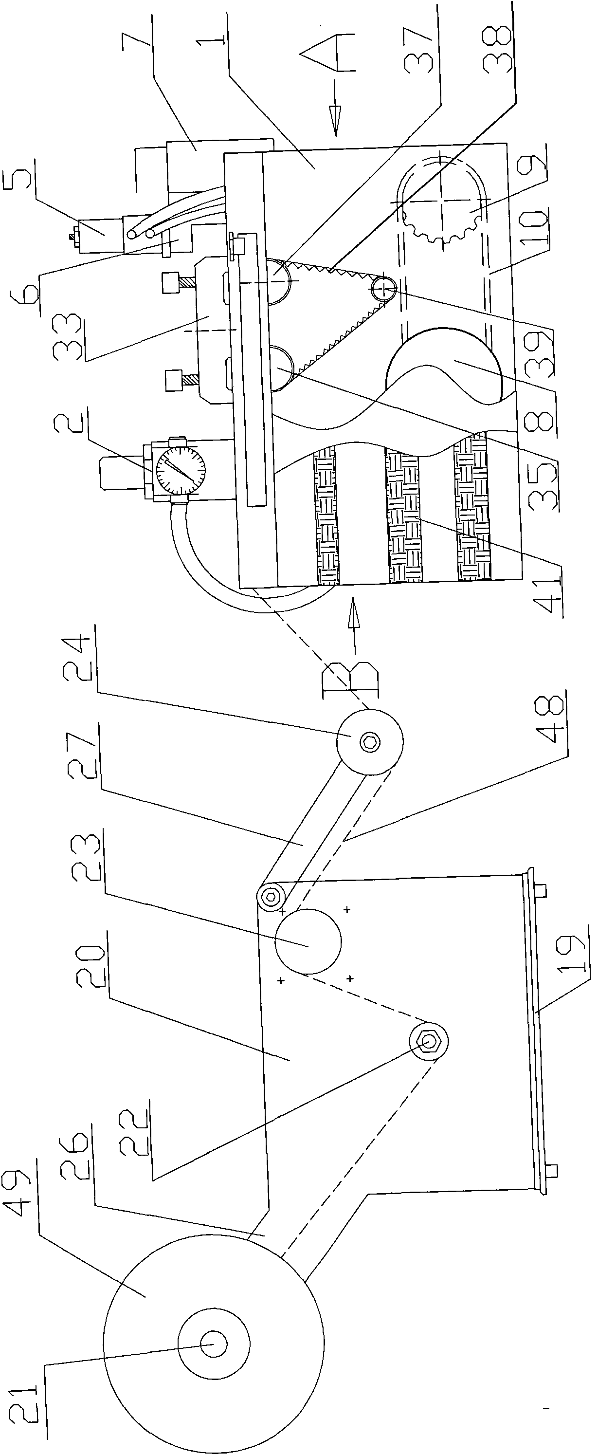
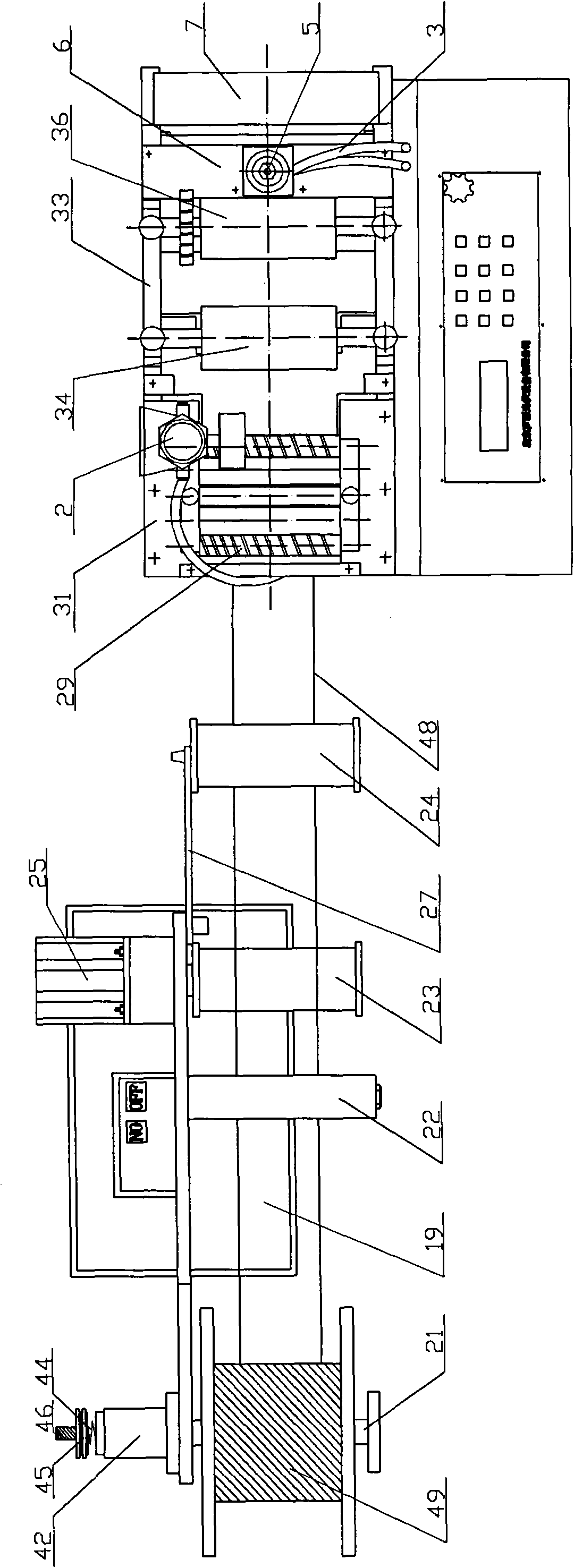
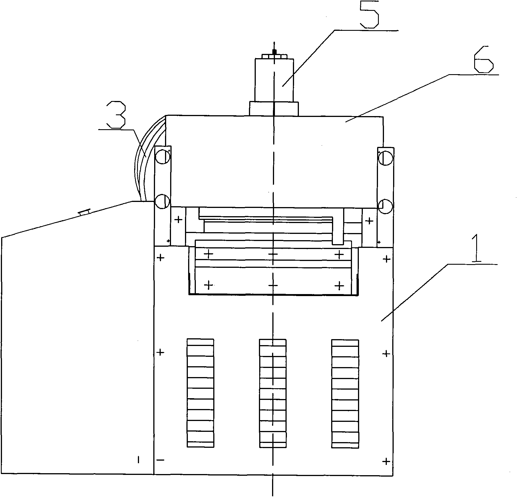
[0033] like Figures 1 to 7 As shown, the fully automatic welding strip cutting and bending machine of the present invention includes a feeding mechanism, a leveling mechanism, a bending mechanism, a cutting mechanism and a box body 1,

[0034] The bending mechanism includes an oil-water separator 2 fixed on the side of the box body 1, a pipeline 3, a bending frame 4, a cylinder 5 and a cylinder frame 6, one end of the oil-water separator 2 is connected to the air source, and the other end of the oil-water separator 2 passes through the pipeline 3 is connected with the cylinder 5, the cylinder 5 is fixed on the cylinder frame 6, the cylinder shaft 47 of the cylinder 5 is connected with the bending track frame 4, and the cylinder frame 6 is fixed on the fixed frame 7 at the discharge end of the casing 1.

[0035] The cutting mechanism includes a motor 8, an eccentric sprocket 9, a chain 10, an eccentric shaft 11, a lower cutter 12 and an upper cutter 13, the lower cutter 12 is ...


PUM


Abstract

The invention relates to a full-automatic welding strip cutting bender, which is characterized by comprising an emptying mechanism, a levelling mechanism, a bending mechanism, a cutting mechanism and a box body, wherein one end of the oil-water separator of the bending mechanism is connected with a gas resource, and the other end of the oil-water separator is connected with a cylinder by a pipeline; the cylinder is fixed on a cylinder frame; the cylinder shaft of the cylinder is connected with a bending path frame; the cylinder frame is fixed on a fixed mount on the discharge end of the box body; the lower cutter of the cutting mechanism is fixed on the lower end of the fixed mount; the upper cutter is fixed on an upper cutter frame capable of moving up and down; a motor is connected with one of two eccentric sprockets with same eccentricity, and the eccentric sprockets are fixed on an eccentric shaft by a chain; two eccentric sprockets are fixedly connected with two ends on the bottom of the upper cutter frame via a link block; a small eccentric wheel with a photosenser is fixed in the middle of the eccentric shaft between two eccentric sprockets; and a photo-groove is arranged near the position below the small eccentric wheel. The invention improves production efficiency, lowers labour cost and improves product quality.

Description

technical field [0001] The invention relates to a cutting and bending mechanism for a photovoltaic solar energy ribbon, in particular to a fully automatic ribbon cutting and bending machine. Background technique [0002] In the prior art, the bending and cutting of the welding strips are all manually operated, the speed is slow, the precision is low, and the huge number of welding strips is not easy to count, and the length specifications of the cutting strips are prone to defective products, and the bending The uniformity is difficult, and the work efficiency is extremely low, which virtually brings huge pressure to the production cost of the enterprise. [0003] Therefore, how to provide a fully automatic welding strip cutting machine to completely solve the low efficiency brought by manual operation, high labor cost, low cutting accuracy, difficult counting, and difficult bending uniformity are actually one of the current important issues. one. Contents of the inventio...

Claims


Application Information

Patent Timeline
Patent Type & Authority Applications(China)
IPC IPC(8): B21D5/00B21D1/00B26D1/06B26D5/08B26D7/28B26D7/06B26D7/00
Inventor 沈卫冲
Owner 启东市罗源光伏设备有限公司
Learn More