Splenial bone implanting handle

A technology of implantation and bone clamping, which is applied in the field of medical devices, can solve the problems of increasing the difficulty of operation, not having timely fastening and loosening of bone blocks, etc., and achieves the effect of simple operation, high reliability and safety

Inactive Publication Date: 2010-09-22
成都云杉科技有限公司
View PDF4 Cites 0 Cited by
  • Summary
  • Abstract
  • Description
  • Claims
  • Application Information

AI Technical Summary

Problems solved by technology

The disadvantage of this device is that it can only push the bone block, and does not have the function of fastening and loosening the bone block in a timely manner, so the positioning plate and the bone block often slip away during the bone grafting process. situation, which increases the difficulty of operation

Method used


Image

  • Splenial bone implanting handle
  • Splenial bone implanting handle
  • Splenial bone implanting handle

Examples


Embodiment Construction

[0011] The present invention will be further described below in conjunction with the accompanying drawings and embodiments.

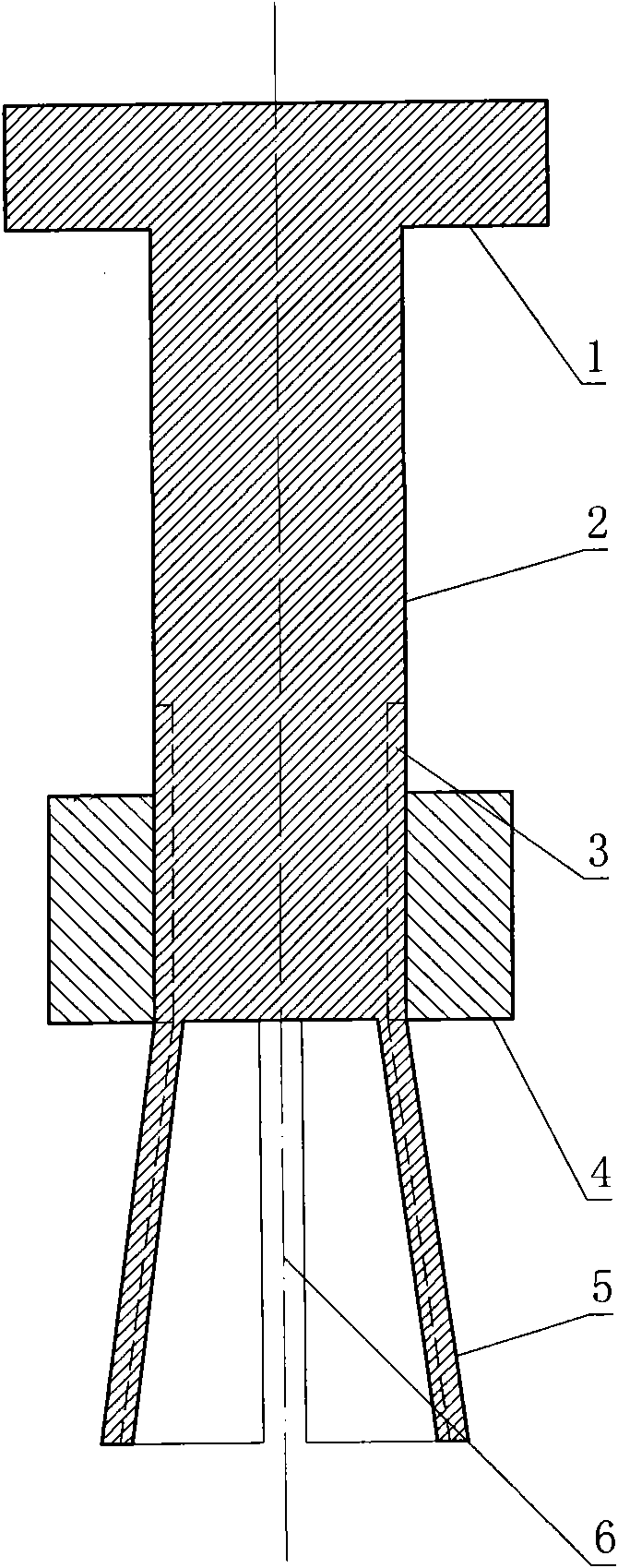
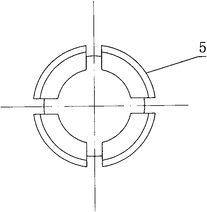
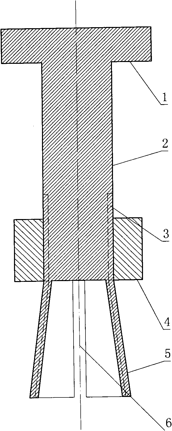
[0012] The bone clamp implant handle is composed of a stress cap 1, a handle 2, a thread 3, a fastening nut 4, a contraction tube 5 and a deformation seam 6. The handle 2 is a cylinder with threads 3 on the side wall at the lower end. The upper end of the handle 2 is a flat cylindrical stress cap 1 integrated with the handle 2. An integral cylindrical shrink tube 5 whose outer wall has a small taper at the top and a large taper at the bottom. There are threads on the outer wall of the shrink tube 5 . The outer wall of the shrink tube 5 has four evenly distributed deformation seams 6 , and the width of each deformation seam 6 is three times greater than the wall thickness of the deformation seams 6 . The junction of the handle 2 and the shrink tube 5 is covered with a fastening nut 4 threadedly combined with the handle 2 .

[0013] During operation, f...


PUM


Abstract

The invention relates to the technical field of medical devices, in particular to a splenial bone implanting handle. The splenial bone implanting handle consists of a force-bearing cap, a grab handle, threads, a fastening nut, a shrink cylinder and deformation joints. The grab handle is a cylinder with the thread on the side wall at the lower end, the flat cylindrical force-bearing cap which is integrated with the grab handle into a whole is arranged at the upper end of the grab handle, and the cylindrical shrink cylinder which is integrated with the grab handle into the whole and has conicity which is small at top and big at bottom on the outer wall is arranged at the lower end of the grab handle. The thread is arranged on the outer side wall of the shrink cylinder. Four deformation joints are uniformly distributed on the outer side wall of the shrink cylinder, and the width of each deformation joint is larger than the wall thickness of the deformation joint by three times. The fastening nut which is combined with the grab handle through the thread is sheathed on the junction of the grab handle and the shrink cylinder. The splenial bone implanting handle has the functions of fastening and loosening a bone block at appropriate time, and can lead the operation to be simpler and more convenient and lead the surgery to have higher reliability and safety.

Description

technical field [0001] The invention relates to the technical field of medical instruments, in particular to a bone clip implant handle. Background technique [0002] Bone grafting is often needed in orthopedic surgery. In order to fix the bone graft better, it is necessary to adopt a bone implant handle, which consists of a handle, brackets and positioning plates positioned at both ends of the handle. The disadvantage of this device is that it can only push the bone block, and does not have the function of fastening and loosening the bone block in a timely manner, so the positioning plate and the bone block often slip away during the bone grafting process. situation, which increases the difficulty of operation. Contents of the invention [0003] In order to solve the deficiencies of the prior art, the invention provides a bone clamping implant handle capable of fastening and loosening bone blocks in due course. [0004] The solution to solve the technical problem of the...

Claims


Application Information

Patent Timeline
IPC IPC(8): A61B17/56
Inventor 许廷森
Owner 成都云杉科技有限公司
Why Eureka
Try Eureka