
Uplink carrier scheduling method for carrier aggregation communication system, base station and user equipment

A scheduling method and carrier aggregation technology, applied in wireless communication, electrical components, etc., can solve the problems of uplink transmission data loss, data loss, multiple retransmissions, etc., and achieve the effect of reducing error rate and reasonable scheduling

Active Publication Date: 2010-09-15
北京万海云科技有限公司
View PDF4 Cites 44 Cited by
  • Summary
  • Abstract
  • Description
  • Claims
  • Application Information

AI Technical Summary

Problems solved by technology

With this method, the eNB cannot correctly determine which uplink CCs should be added to the UE, and it is possible to add and schedule CCs with poor channel quality to the UE, resulting in the loss of uplink transmission data, or the need for multiple retransmissions, and low communication efficiency
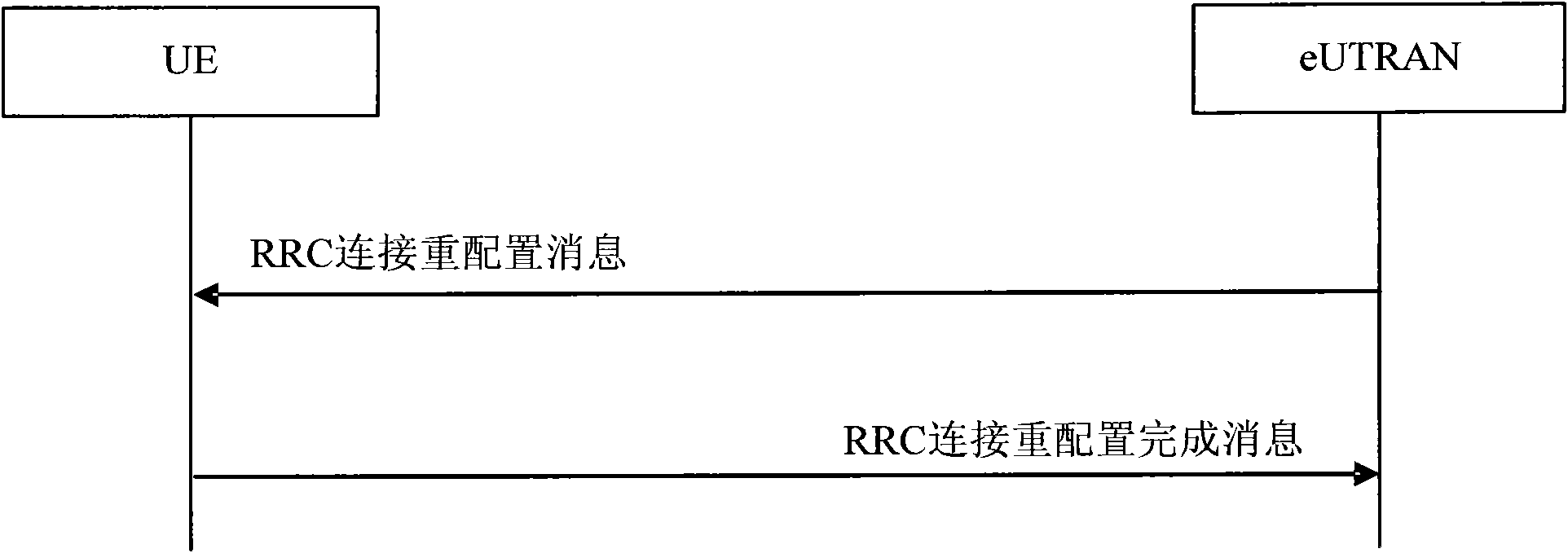
Moreover, in the current scheduling method for uplink CCs, the adjustment of CCs includes the addition, deletion or replacement of CCs. When the eNB deletes an uplink CC of the UE through the RRC connection reconfiguration message, even if the uplink CC is restored later The eNB cannot know the good communication quality, so it cannot be added to the UE's uplink CC set when the CC quality is restored
[0007] In short, with the uplink carrier scheduling method of the existing carrier aggregation system, the eNB cannot make a reasonable decision on the uplink carrier scheduling, and the system uses this scheduling method for uplink transmission to easily cause data loss, resulting in a high system error rate

Method used


Image

  • Uplink carrier scheduling method for carrier aggregation communication system, base station and user equipment
  • Uplink carrier scheduling method for carrier aggregation communication system, base station and user equipment
  • Uplink carrier scheduling method for carrier aggregation communication system, base station and user equipment

Examples


Embodiment Construction

[0043] In order to make the object, technical solution and advantages of the present invention clearer, the present invention will be described in detail below in conjunction with the accompanying drawings and specific embodiments.

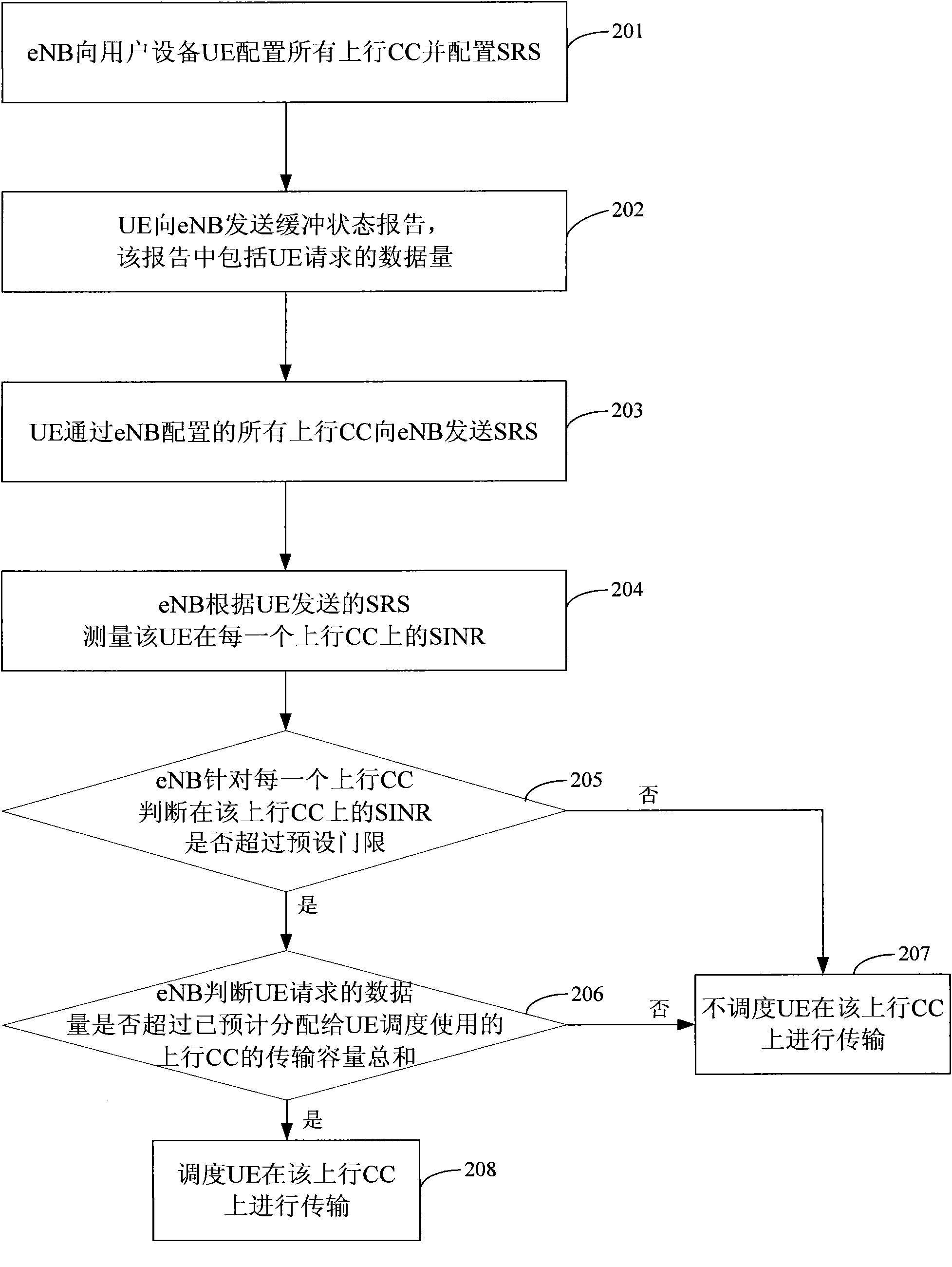
[0044] The basic idea of ​​the present invention is that the eNB configures all uplink CCs to the UE, and at the same time configures a sounding reference signal (SRS) for the UE, and the UE sends the SRS to the eNB through all the uplink CCs, so that the eNB can understand the Based on the quality of the UE on the uplink CC, a reasonable decision is made on whether to schedule the UE to perform transmission on the uplink CC according to the quality of the uplink CC.

[0045] A preferred embodiment is given below to illustrate the uplink carrier scheduling method in the carrier aggregation communication system proposed by the present invention. figure 2 It is a flowchart of an uplink carrier scheduling method in a carrier aggregation communication ...


PUM


Abstract

The invention discloses an uplink carrier scheduling method for an LTE (Long Term Evolution) carrier aggregation communication system. In the uplink carrier scheduling method, an eNb (evolved NodeB) configures all uplink CCs (Component Carriers) to UE (User Equipment) and configures an SRS (Sensing Reference Signal), the UE sends the SRS to the eNB through all the uplink CCs configured by the eNB, the eNB measures the SINR of the UE on each uplink CC based on the SRS sent by the UE, and the eNB judges whether the SINR (Signal to Interference Plus Noise Ratio) of the uplink CC exceeds a preset threshold; and if so, the eNB schedules the UE to carry out transmission on the uplink CC, or else, the eNB does not schedule the UE to carry out transmission on the uplink CC. The invention also discloses the eNB and the UE in an LTE carrier aggregation communication system. By using the uplink carrier scheduling method, the eNB and the UE, the eNB can clearly know the quality of the UE on each uplink CC, so that the eNB can make a decision based on the quality the uplink CC when judging whether to schedule the UE to carry out transmission on the uplink CC, thereby being capable of reasonably scheduling the uplink carrier.

Description

technical field [0001] The present invention relates to mobile communication technology, in particular to an uplink carrier scheduling method, base station (eNB) and user equipment (UE) in a carrier aggregation communication system. Background technique [0002] In a long-term evolution (LTE) system, each UE only supports one uplink carrier and one downlink carrier, and does not involve adding a carrier for service transmission to the UE. In the subsequent evolution of LTE technology (LTE-A) system, in order to obtain a higher peak data rate, the Third Generation Partnership Project (3GPP) proposes that the UE supports data transmission on multiple component carriers (CCs) to obtain a higher peak data rate. Large bandwidth, for example, the maximum bandwidth can reach 100MHz. This technique is called Carrier Aggregation (CA), also known as Bandwidth Aggregation. [0003] In order to realize asymmetric aggregation of uplink and downlink, the LTE-A carrier aggregation system...

Claims


Application Information

Patent Timeline
IPC IPC(8): H04W24/10H04W72/12H04W88/08
Inventor 李国荣白杰
Owner 北京万海云科技有限公司
Learn More