
Non-contact type superconducting tape current-carrying capacity measuring device

A technology of superconducting tape and current-carrying capacity, applied in the field of superconducting engineering, can solve the problems of guiding, conveying and taking-up equipment, measuring the residual magnetism and unable to realize the current-carrying capacity test of the tape, etc. Effects of speed and measurement efficiency, design complexity reduction

Inactive Publication Date: 2010-09-15
TSINGHUA UNIV
View PDF4 Cites 9 Cited by
  • Summary
  • Abstract
  • Description
  • Claims
  • Application Information

AI Technical Summary

Problems solved by technology

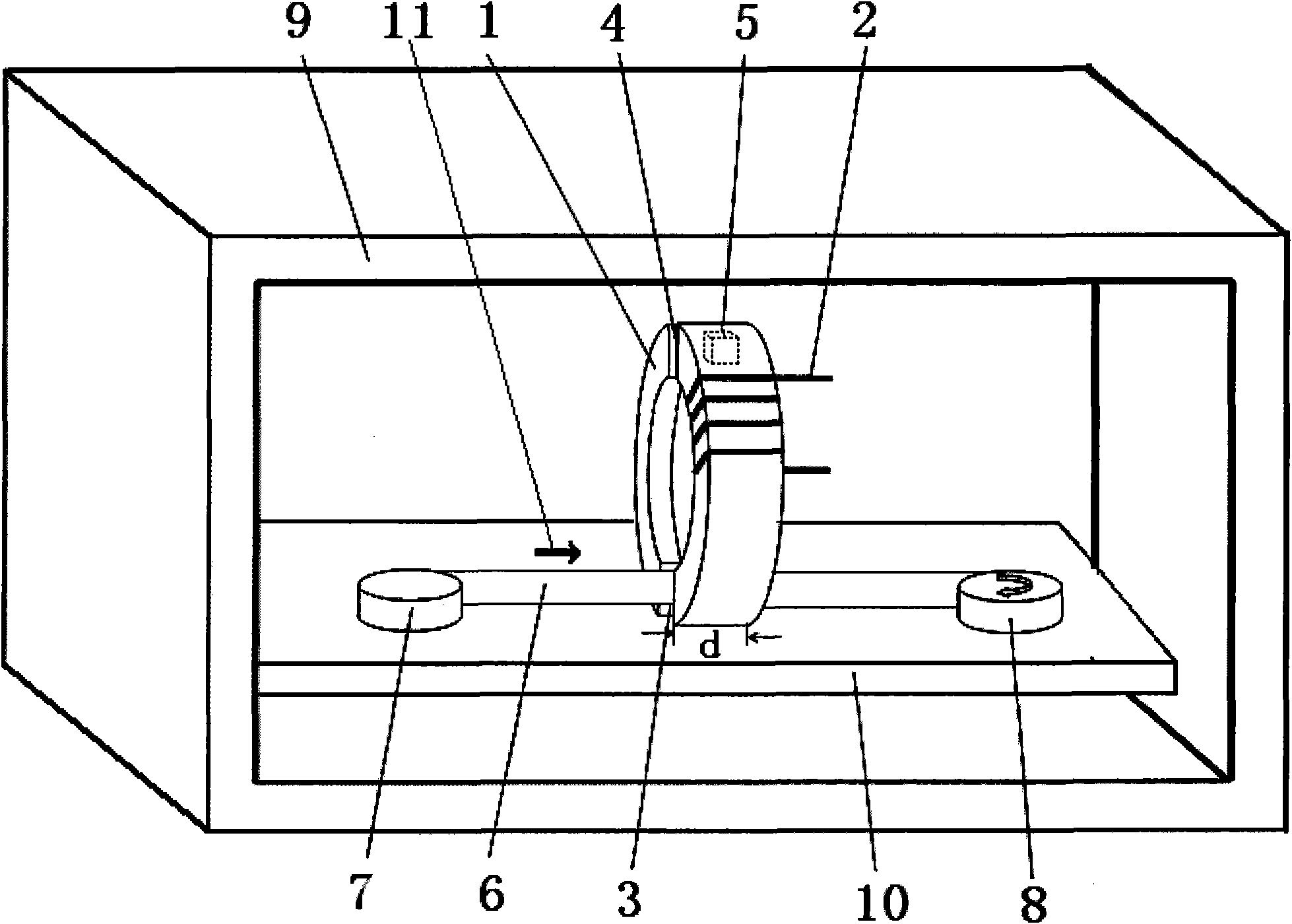
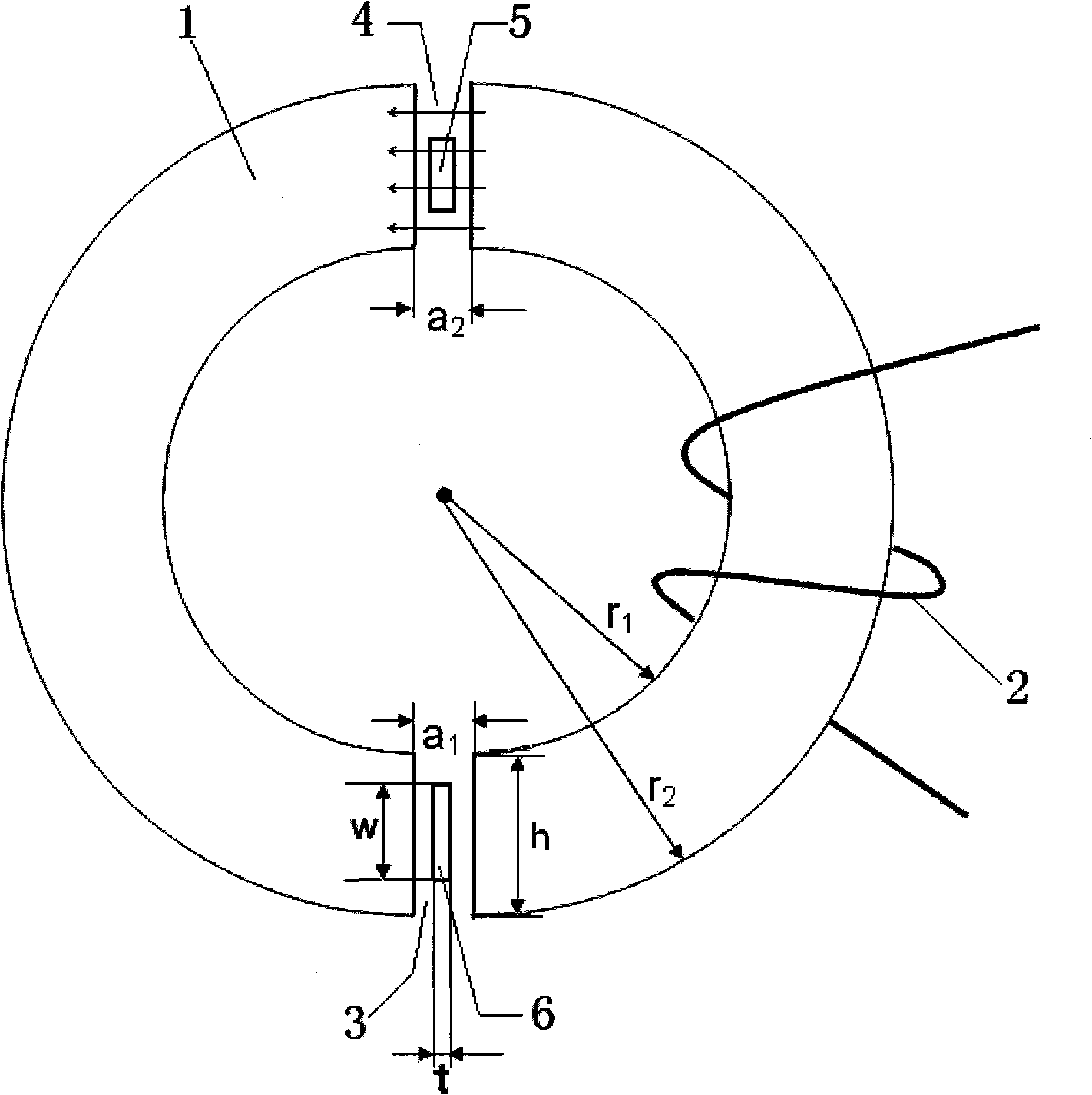
[0007] The purpose of the present invention is to solve the problem that the current-carrying capacity test of the strip in various external magnetic fields and various penetration states cannot be realized by using the method of measuring the residual magnetism in the prior art, and the measured data are not fully reflected in different working conditions. The problem of the current carrying capacity information under the magnetic field, the present invention is based on a single magnetic circuit, by measuring the reverse driving capacity of the magnetic circuit by the circular current induced by the external magnetic field in the superconducting strip to reflect the current carrying capacity, and proposes a non- The contact type superconducting strip current-carrying capacity measuring device is characterized in that the detection magnetic circuit is vertically fixed on the base 10, and the detection magnetic circuit includes an iron core 1, an excitation coil 2, a sample slit 3 and a measurement slit 4, and the installation The first guide wheel 7 and the second guide wheel 8 on the base 10 cooperate with the pay-off equipment and the take-up equipment outside the liquid nitrogen container 9 to form a continuous transmission device for superconducting strips, the first guide wheel 7 and the second guide wheel 8 are respectively placed on both sides of the detection magnetic circuit, the first guide wheel 7, the sample slit 3 and the second guide wheel 8 are on the same straight line, the sample 6 of the high temperature superconducting strip passes through the first guide wheel from the external pay-off equipment. The wheel 7 guides through the sample slit 3 and then is guided by the second guide wheel 8 to the external take-up device. The sample movement direction 11 is from the first guide wheel 7 to the second guide wheel 8; the base 10 is placed in a liquid nitrogen container 9, when the device works, the detection magnetic circuit and the sample 6 are immersed in liquid nitrogen; in the detection magnetic circuit, the excitation coil 2 is wound on the iron core 1, and the iron core 1 of the detection magnetic circuit, the sample slit 3 and the measurement The slit 4 forms a closed magnetic circuit, and the magnetic field probe 5 for measuring the magnetic induction intensity is placed in the measurement slit 4

Method used


Image

  • Non-contact type superconducting tape current-carrying capacity measuring device
  • Non-contact type superconducting tape current-carrying capacity measuring device
  • Non-contact type superconducting tape current-carrying capacity measuring device

Examples


Embodiment Construction

[0025] The working principle, measurement process and test results of the non-contact superconducting strip current-carrying capacity measurement device based on the single magnetic circuit method will be described in detail below in conjunction with the accompanying drawings and embodiments.

[0026] A schematic diagram of an embodiment of a non-contact superconducting strip current-carrying capacity measuring device is shown in figure 1As shown, the detection magnetic circuit is vertically fixed on the base 10 , and the detection magnetic circuit includes an iron core 1 , an excitation coil 2 , a sample slit 3 and a measurement slit 4 . In order to realize the continuous measurement of the long strip, the first guide wheel 7 and the second guide wheel 8 installed on the base 10 cooperate with the pay-off equipment and the take-up equipment outside the liquid nitrogen container 9 to form a superconducting strip continuous transmission device, The first guide wheel 7 and the s...


PUM


Abstract

The invention belongs to the field of superconducting electrical engineering, particularly relates to a non-contact type superconducting tape current-carrying capacity measuring device. In a current transmission performance continuous measuring method based on a signal magnetic path, a detection magnetic path is vertically fixed on a base; and an iron core, a sample slit, a measuring slit and an exciting coil of the detection magnetic path form a closed detection magnetic path. Under the conditions of liquid nitrogen at low temperature, the exciting coil is electrified to generate a fixed magnetic field at the sample slit and the measuring slit; a sample passes through the sample slit to induce annular current in the sample; and magnetic induction intensity change generated when the detection magnetic path is reversely driven by the annular current is measured at the measuring slit to reflect the current-carrying capacity of the tape. The single magnetic path device has the same advantages of high speed and favorable repeatability as double magnetic paths, can also measure the current-carrying capability of the tape i different applied magnetic fields and different magnetic filed penetrativities and is especially suitable for continuously measuring the current-carrying capacity of the ultralong and superconducting tape.

Description

technical field [0001] The invention belongs to the field of superconducting electrical engineering, in particular to a device for measuring the current-carrying capacity of a non-contact superconducting strip. Background technique [0002] Superconducting materials provide important technical support for a green and sustainable energy economy. Superconducting cables and superconducting fans are gradually being used in civilian applications. The era of large-scale use of high-temperature superconducting materials is coming. Current-carrying performance is the most basic parameter reflecting the performance of superconducting strips. The "four-lead method" is generally adopted to measure the critical current to reflect the current-carrying performance of the current, that is, to load the current at both ends of the sample and observe the voltage signal. As the current increases, the critical current of the superconducting strip is determined by observing the increase of the ...

Claims


Application Information

Patent Timeline
Patent Type & Authority Applications(China)
IPC IPC(8): G01R19/00
Inventor 顾晨瞿体明韩征和邹圣楠
Owner TSINGHUA UNIV
Learn More