
Audio and video synchronized method and device as well as data receiving terminal

A technology of video data and audio data, applied in the direction of pulse modulation TV signal transmission, etc., can solve the problems of video quality degradation, inability to completely solve the problem of out-of-sync, audio and video out-of-sync, etc., to improve audio quality and avoid audio and video out-of-sync Synchronized, smooth sound effect

Active Publication Date: 2012-07-18
LEADCORE TECH
View PDF0 Cites 0 Cited by
  • Summary
  • Abstract
  • Description
  • Claims
  • Application Information

AI Technical Summary

Problems solved by technology

[0004] 3G services stipulate that the bit error rate can reach 10 -4 to 10 -6 , in the case of poor signal quality, the bit error rate will reach 10 -3 , so due to bit errors, the video quality will be degraded
[0014] The distortion indication H223SkewIndication in H.245 only includes the audio and video sampling time of the sending end, the encoding delay of the encoder, and the buffer delay of the sending end. It indicates that only the difference caused by the sending end causes the audio and video to be out of sync. It does not include changes in the timing of audio and video data caused by network jitter or network errors and the cache information of audio and video data at the receiving end. This method can only partially solve the phenomenon of audio and video synchronization, and cannot completely solve the problem of out-of-sync
Because the frame rate of the video is constantly changing, there are network jitters or network errors, data buffering at the receiving end, etc., after a period of video calls, the audio and video will still be out of sync.

Method used


Image

  • Audio and video synchronized method and device as well as data receiving terminal
  • Audio and video synchronized method and device as well as data receiving terminal
  • Audio and video synchronized method and device as well as data receiving terminal

Examples


Embodiment Construction

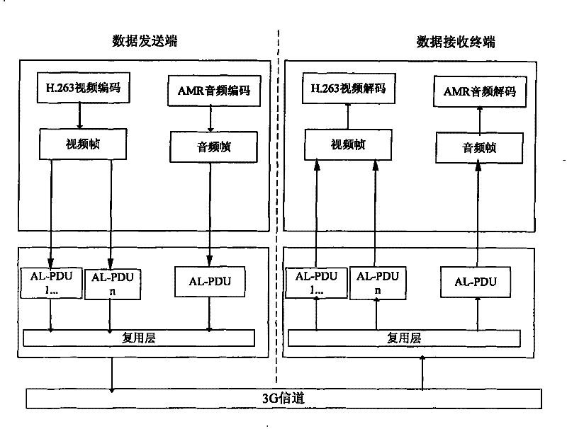
[0064] figure 1 A system block diagram according to an embodiment of the present invention is shown. Among them, according to the 3G-324M standard, in the 3G324M protocol stack 100, the H.223 protocol stack 110 is used for multiplexing and separation of voice, video, user data and control data; the H.263 codec 120 is used for video For encoding, an AMR codec 130 is used for audio encoding, and an H.245 protocol stack 140 is also used. The video device 150 can provide video data to the H.263 codec 120 , and the voice device 160 can provide audio data to the AMR codec 130 . Correspondingly, the data received via the 3G channel 170 can be processed by the H.223 protocol stack 110, and then decoded by the H.263 codec 120 and the AMR codec 130 respectively, and then sent to the video device 150 and the audio device 160 for playback. . Among them, the H.223 protocol stack 110 can be further divided into a multiplexing layer (MUXLayer) and an adaptation layer.

[0065] For the sp...


PUM


Abstract

The invention relates audio and video synchronized method and device as well as a data receiving terminal for realizing the audio and video synchronization. The method comprises the following steps of: respectively adding a video time stamp and an audio time stamp in sent video data and audio data at a data sending end, as well as acquiring the received audio data and corresponding audio time stamp and recording the current local clock at a data receiving terminal; acquiring the received video data and the corresponding video time stamp to form a complete video data frame, and recoding the current local clock; calculating the audio dithering time according to the audio time stamp of the audio data and the current local clock; sending one frame of audio data to an audio decoder every othera preset time, and generating a silent frame to be sent to the audio decoder if the audio data is discarded; and referencing the currently playing audio time stamp, the video time stamp of a video data frame to be processed and the audio dithering time to determine whether the video data frame is handed to the video decoder.

Description

technical field [0001] The invention relates to low bit rate wireless channel transmission, in particular to an audio and video synchronization method and device for a low bit rate wireless channel terminal in a high bit error rate environment, and a data receiving terminal for realizing video and audio synchronization. Background technique [0002] In a low bit rate wireless channel terminal in a high bit error rate environment, the audio and video are out of sync due to the processing of the sending end, network, and receiving end. The main reasons are: 1. The control of the video bit rate by the sending end will cause 2. Due to network jitter or network error, the timing of audio and video data will change; 3. Due to the buffering of audio and video data at the receiving end, the playback is delayed; these three reasons are in the actual development process. Actually exist, however the audio and video out-of-sync caused by these reasons has not been effectively solved. ...

Claims


Application Information

Patent Timeline
Patent Type & Authority Patents(China)
IPC IPC(8): H04N7/52H04N7/56
Inventor 朱胜裘风光
Owner LEADCORE TECH
Learn More