Positioner

A positioner and workbench technology, which is applied in the field of positioners, can solve the problem of increasing the height of the positioner

Active Publication Date: 2010-09-01
PANASONIC CORP
View PDF1 Cites 9 Cited by
  • Summary
  • Abstract
  • Description
  • Claims
  • Application Information

AI Technical Summary

Problems solved by technology

As a result, there is a problem that the height of the locator becomes higher

Method used


Image

  • Positioner
  • Positioner
  • Positioner

Examples


Embodiment approach 1

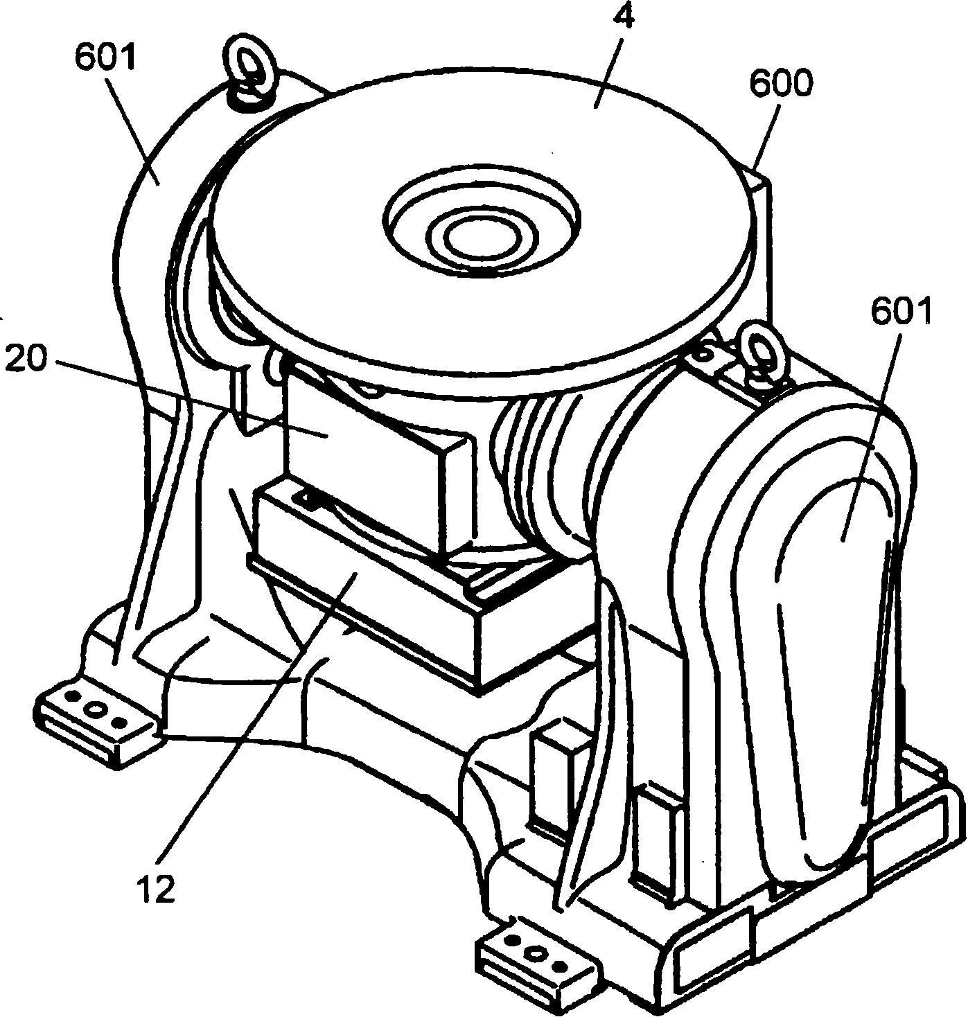
[0076] figure 1 The appearance of the positioner according to Embodiment 1 of the present invention is shown. In the figure, the positioner 600 has a table 4, a frame body 20, and a case 12 as a first case. The positioner 600 is supported by two legs 601 .

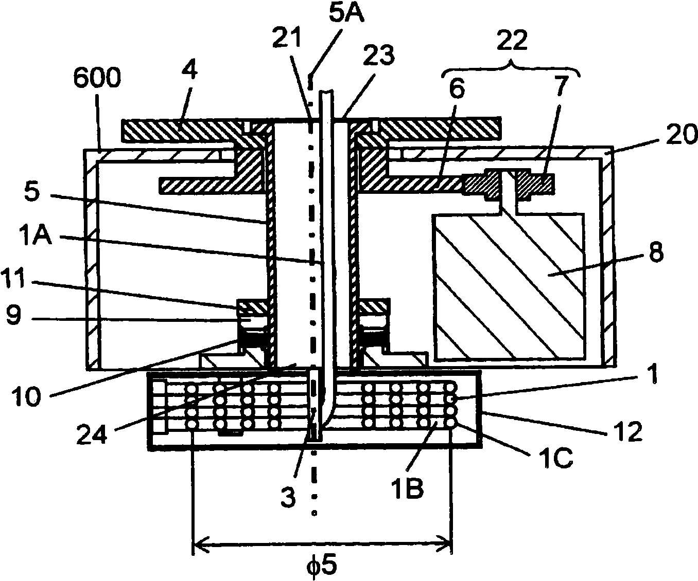
[0077] use Figure 2A The details of the positioner 600 will be described. As shown in the figure, the workbench 4 is arranged on the upper part of the frame body 20 . The table 4 rotates around the rotation center 21 with respect to the housing 20 . Workbench 4 has conductivity. An object to be welded, a jig for attaching the object to the table 4 , and the like are fixed on the table 4 . The motor 8 serving as a driving unit rotates the table 4 in the forward and reverse directions with respect to the rotation center 21 . In Embodiment 1, the positioner 600 has the speed reducer 22 that transmits the power of the motor 8 to the table 4 . The speed reducer 22 has a first gear 6 and a second gear 7 . The first gear...

Embodiment approach 2

[0102] use Figure 10 to Figure 15 Other embodiments of the present invention will be described. However, the same symbols are assigned to the same structures as those in Embodiment 1, and the descriptions are referred to.

[0103] Figure 10 It is a cross-sectional view of a positioner according to Embodiment 2 of the present invention. Figure 11 It is a cross-sectional view of another positioner according to Embodiment 2 of the present invention. Figure 12 It is a perspective view of a fixing tool according to Embodiment 2 of the present invention.

[0104] The positioners 602 and 603 shown in the second embodiment are those in which the fixed shaft 303 as the second winding portion and the winding tube 2 as the second wire are added to the positioner 600 described in the first embodiment.

[0105] and then, Figure 10 The locator 602 is shown with the divider plate 31 inside the housing 12 . The partition plate 31 separates the first wound portion 1B wound around th...


PUM


Abstract

A positioner is equipped with a housing, a table, a drive unit, a tube, a first coil section, and a first cord. The tube has a first open section positioned at the center of rotation of the table, and a second open section connecting to the first open section and positioned on the opposite side from the first open section. The first coil section is positioned outside of the second open section of the tube. The first cord has a first draw-out section and a first take-up section. The first draw-out section is drawn out from the table through the inside of the tube from the second open section. The first take-up section is wound on the first coil section as the table rotates. The number of air tubes or electrical wires drawn out onto the table can be increased while keeping the positioner from becoming much larger.

Description

technical field [0001] The present invention relates to a positioner which changes the direction of a turntable on which an object to be processed is placed when welding, cutting, etc. are performed by an industrial robot, thereby facilitating the processing operation. Background technique [0002] Such as Figure 16 As shown, the conventional positioner has a drive unit 501 inside a housing 500 . A reduction gear 502 is attached to the drive unit 501 . A speed reducer 502A is attached to the cylinder 503 . The cylinder 503 is driven by the driving unit 501 via the reduction gears 502 and 502A. One end of the cylinder 503 is attached to the table 504 so that the center 503A of the cylinder 503 overlaps with the rotation center 504A. A composite wound wire 505 is routed inside the drum 503 . The composite coiled wire 505 is composed of an air tube, an IO signal cable, a power supply cable, a movable communication cable, etc. (hereinafter referred to as “wires”), and is bu...

Claims


Application Information

Patent Timeline
Patent Type & Authority Applications(China)
IPC IPC(8): B23Q1/00B23K37/047B23Q1/52H02G11/02
CPCH02G11/02B23K37/0452H02G11/006
Inventor 永井节高桥涉大原隆靖岩井清次
Owner PANASONIC CORP
Why Eureka
Try Eureka