
Speed changer

A technology of transmission and claw clutch, applied in the direction of gear transmission, transmission control, belt/chain/gear, etc., can solve the problems of unstable performance, high maintenance cost, low mechanical efficiency, etc., to achieve easy operation and continuous production. Good performance and low cost

Inactive Publication Date: 2013-01-30
HUNAN JINLONG MOTOR
View PDF3 Cites 0 Cited by
  • Summary
  • Abstract
  • Description
  • Claims
  • Application Information

AI Technical Summary

Problems solved by technology

[0006] The purpose of the present invention is to solve the problems of high cost, large volume, few functions, few gears, low mechanical efficiency, short life, unstable performance and high maintenance cost in the current transmission technology. The present invention provides a high transmission efficiency, Transmission with small size, more or less gears, fully automatic or manual transmission, long service life, stable performance and low maintenance cost

Method used


Image

  • Speed changer
  • Speed changer
  • Speed changer

Examples


Embodiment Construction

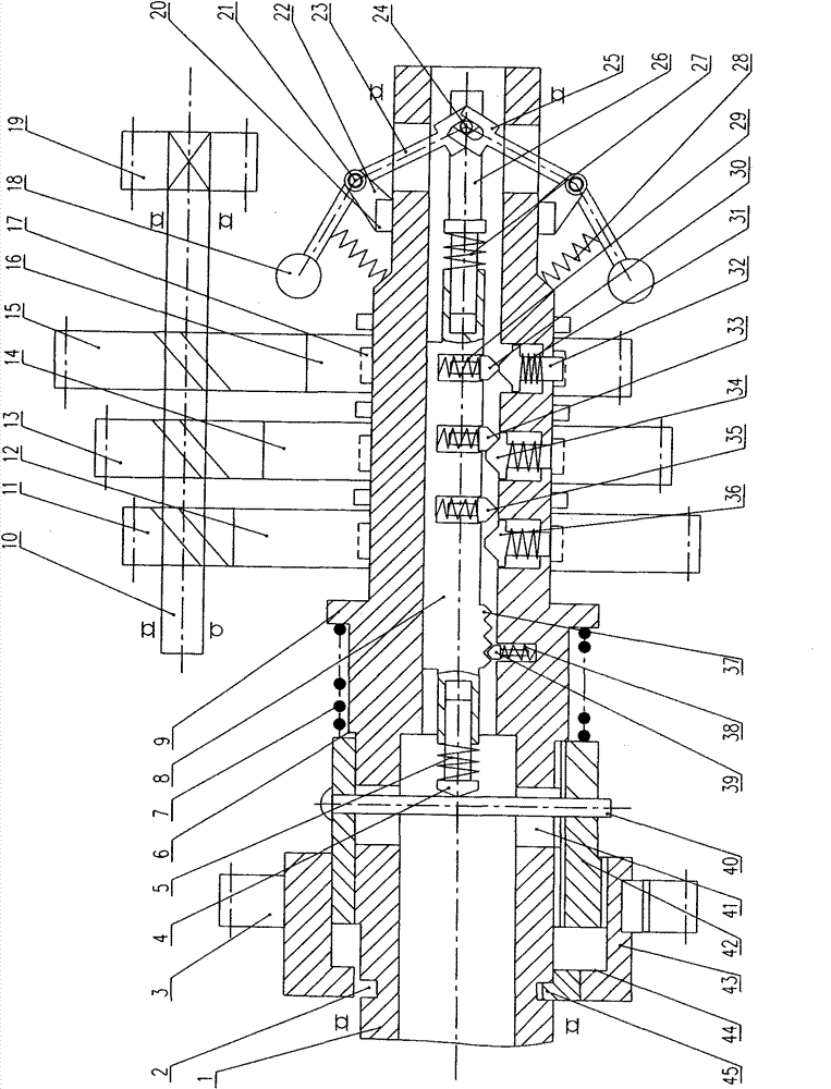
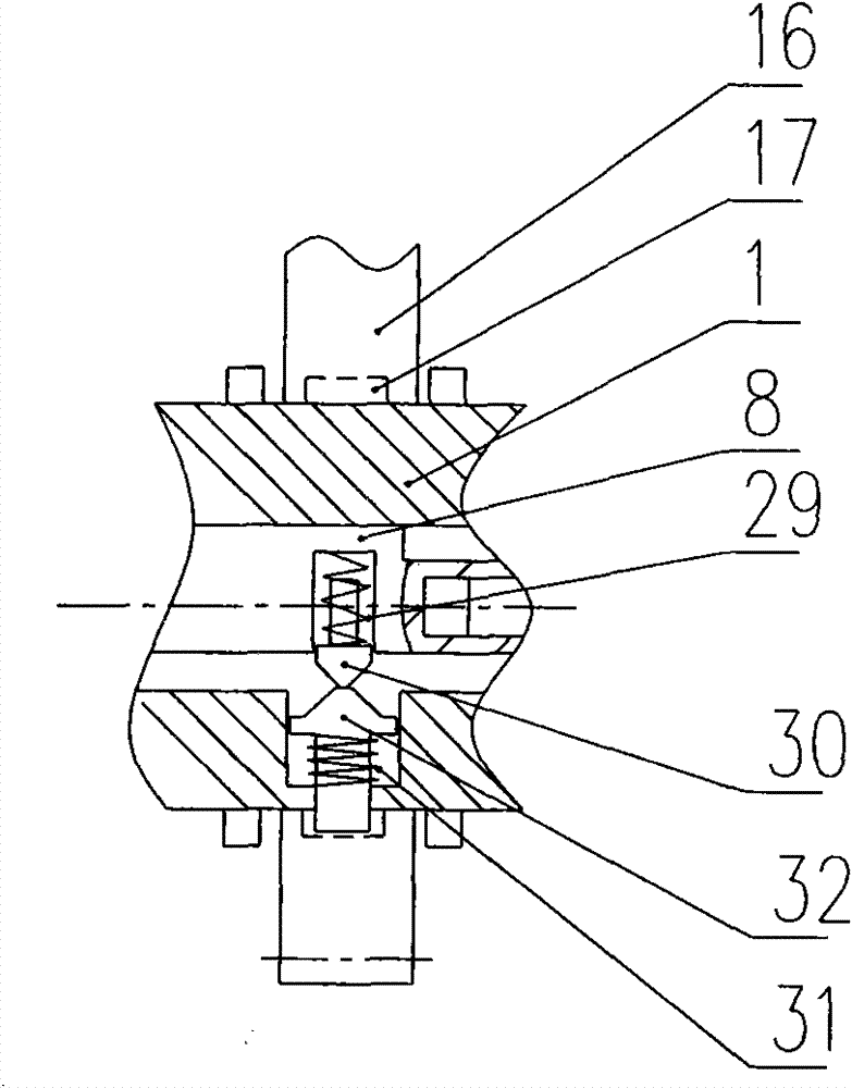
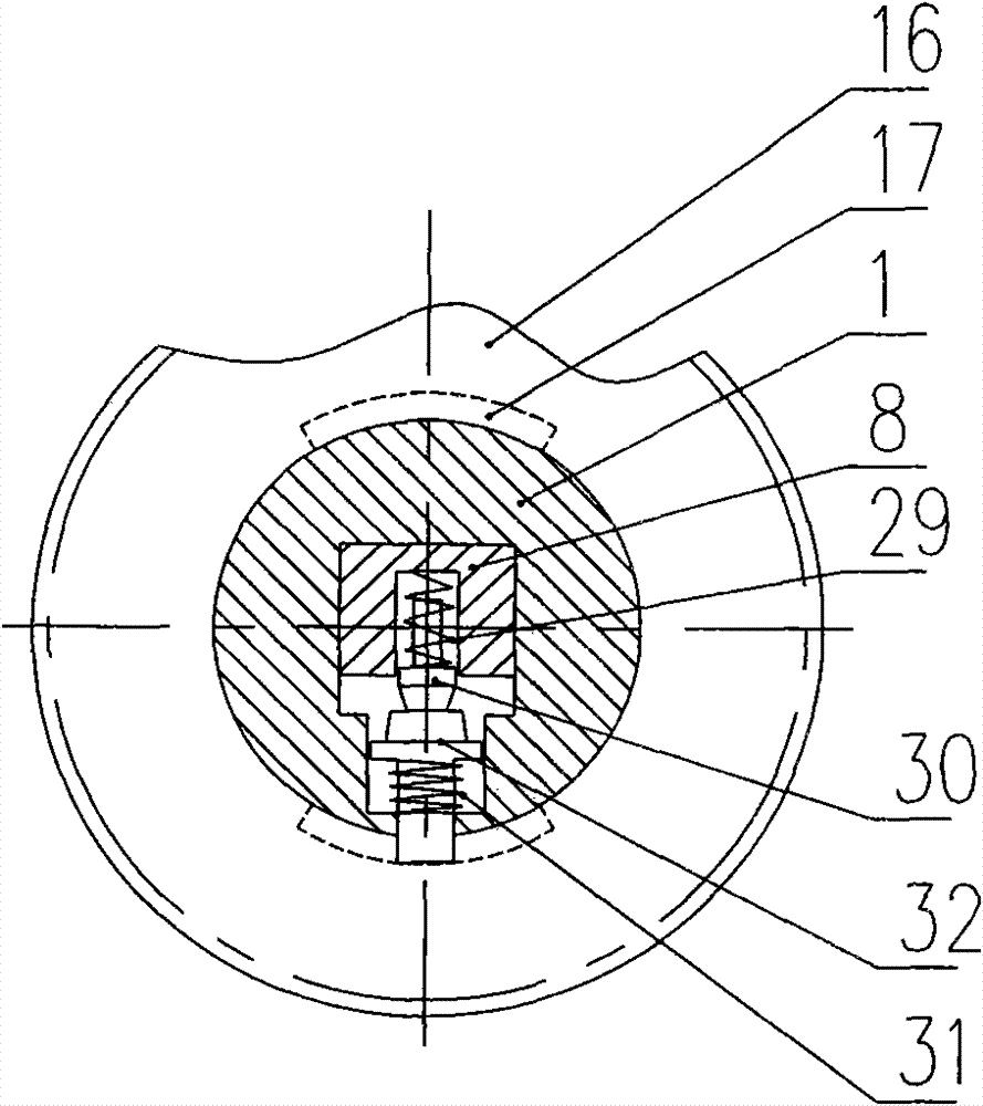
[0034] like figure 1 , figure 2 and image 3 As shown, the power input gear 3 is fixed to the outer casing 43, and one end of the outer casing is processed with an inner circular sliding tooth 45 and a thrust inner ring 44. The sliding tooth 45 is installed on the outer ring groove 2 at one end of the gear shaft 1, and the gear shaft 1 The thrust outer ring 6 is fixed on the top, and the outer sleeve can rotate forward and reverse relative to the gear shaft. The sliding sleeve 42 and the outer sleeve 43 are matched by a helical rack, and the sliding sleeve 42 and the gear shaft 1 are matched by a straight rack or a helical rack. The sleeve 42 is installed between the thrust inner ring 44 of the overcoat and the thrust outer ring 6 of the gear shaft, and the sliding sleeve can reciprocate and axially move between the thrust inner ring of the overcoat and the thrust outer ring of the gear shaft. A compressed spring 7 is installed between an axial end face of the sliding sleev...


PUM


Abstract

The invention discloses a speed changer capable of solving the problems of large size, complex operation, high maintenance cost, and the like of the traditional speed changer. The speed changer has about 97 percent of transmission mechanical efficiency and easy and convenient operation and is characterized in that a power input gear can be fixed with a jacket; a sliding sleeve is matched with the jacket through a helical rack and is matched with a gear shaft through a spur rack; a pin shaft of the sliding sleeve contacts with a push rod of a gear shift shuttle; a crank arm is movably connected with a lug through the pin shaft; a shifting fork forks on a shaft rod of a push-and-pull rod; a hollow cavity or a sliding chute of the gear shaft is internally provided with the gear shift shuttle; the gear shift shuttle is provided with a top bulge; the gear shaft is provided with a sliding key and is assembled with an angle gear matched with a chamfered groove strip and a plurality of gearshift gears; the gearshift gears can be respectively meshed with a driven gear; the driven gear is assembled on a driven shaft; and the driven shaft is fixed with a power output gear. The invention can be used for an epicyclic gear train and realize the full-automatic speed change from two gears to more than ten gears.

Description

technical field [0001] The invention relates to a transmission for vehicle transmission, in particular to automatic and manual transmission and transmission devices for small rickshaws, electric vehicles and motor vehicles, which belongs to the technical field of mechanical transmission. Background technique [0002] The existing continuously variable automatic transmission has low mechanical efficiency, easy damage, high cost, and unstable performance; the mechanical automatic transmission is large in size and poor in shifting quality; the hydraulic automatic transmission has low transmission efficiency and is expensive; the mechanical manual transmission is cumbersome to operate, The mechanical efficiency is low and the use is not convenient enough. [0003] Among the existing technologies, the fully automatic transmission announced by the Chinese utility model patent (patent number: ZL200820015549.8) is that the speed change rod moves back and forth in the hollow shaft ca...

Claims


Application Information

Patent Timeline
Patent Type & Authority Patents(China)
IPC IPC(8): F16H59/08F16H3/00F16H61/04F16H63/30B60K17/06
Inventor 向永川
Owner HUNAN JINLONG MOTOR
Learn More