
Method for improving radiation performance of antenna and a mobile terminal

A mobile terminal and antenna radiation technology, which is applied to antennas, resonant antennas, antenna components, etc., can solve the problems of poor performance of mobile terminal antennas and the influence of antenna debugging, and achieve the effect of ensuring radiation performance

Inactive Publication Date: 2010-08-25
ZTE CORP
View PDF3 Cites 37 Cited by
  • Summary
  • Abstract
  • Description
  • Claims
  • Application Information

AI Technical Summary

Problems solved by technology

However, the location of reserved grounding points and the number of grounding points will have a great impact on antenna debugging
When the location of the reserved grounding points is inappropriate or the number of reserved grounding points is not enough, the performance of the mobile terminal antenna will be very poor
For the current mobile terminal design, in order to ensure the durability and decoration needs of the mobile terminal, it is almost unavoidable to set metal parts on the mobile terminal body.

Method used


Image

  • Method for improving radiation performance of antenna and a mobile terminal
  • Method for improving radiation performance of antenna and a mobile terminal
  • Method for improving radiation performance of antenna and a mobile terminal

Examples


Embodiment Construction

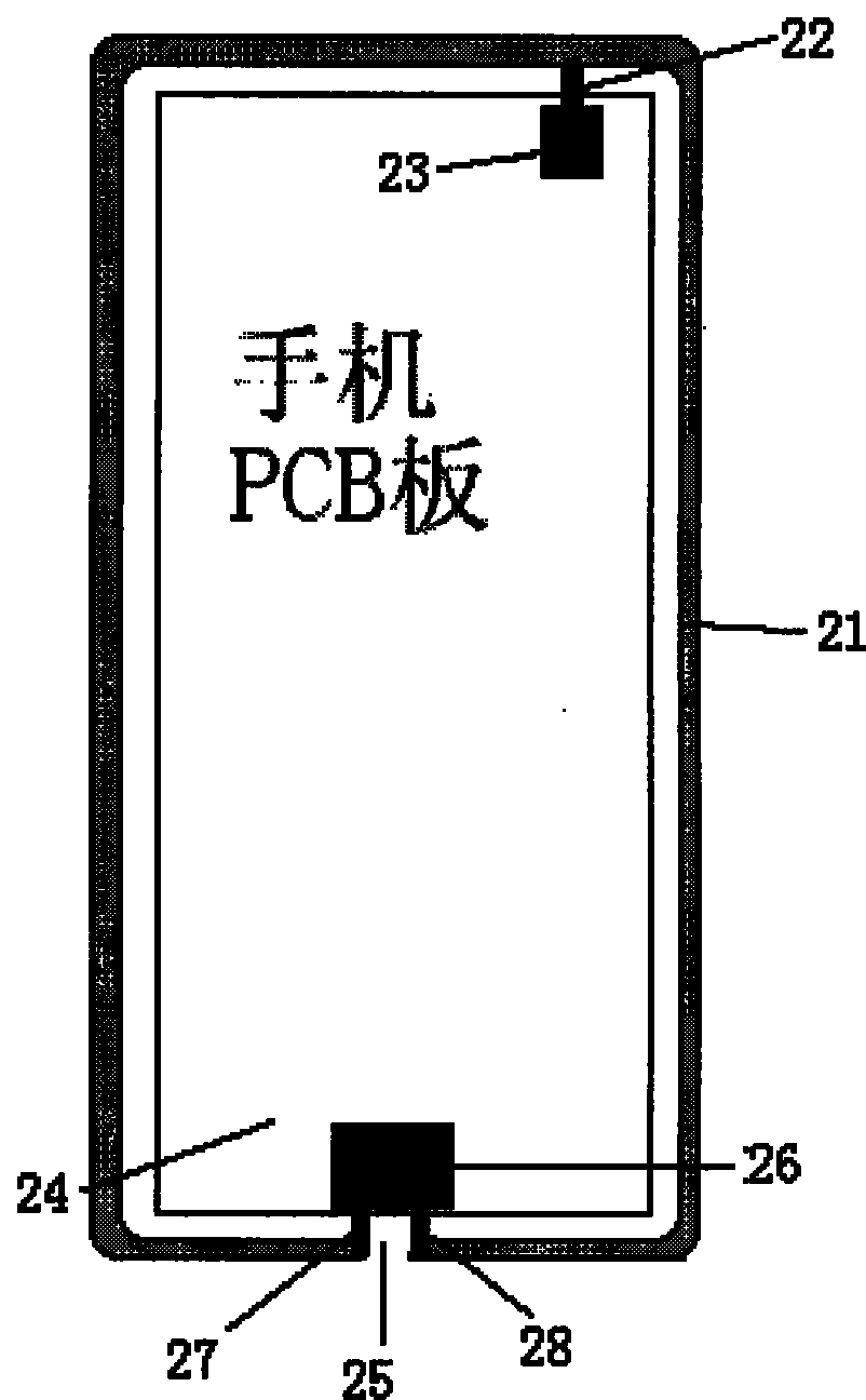
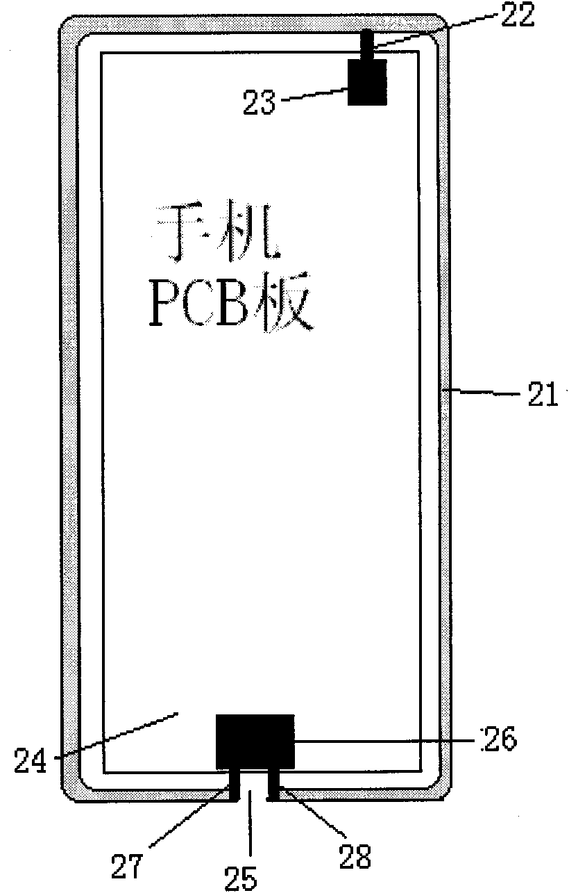
[0025] The basic idea of ​​the present invention is: on the conductive part (mainly metal part) that is arranged on the mobile terminal body, set the feeder line of mobile terminal antenna, and connect with the feed point or feed lead wire, grounding point or grounding of mobile terminal antenna The lead wires are connected separately, and the length of the provided feeder wires is more than 90mm.

[0026] In order to make the object, technical solution and advantages of the present invention clearer, the present invention will be further described in detail by citing the following embodiments and referring to the accompanying drawings.

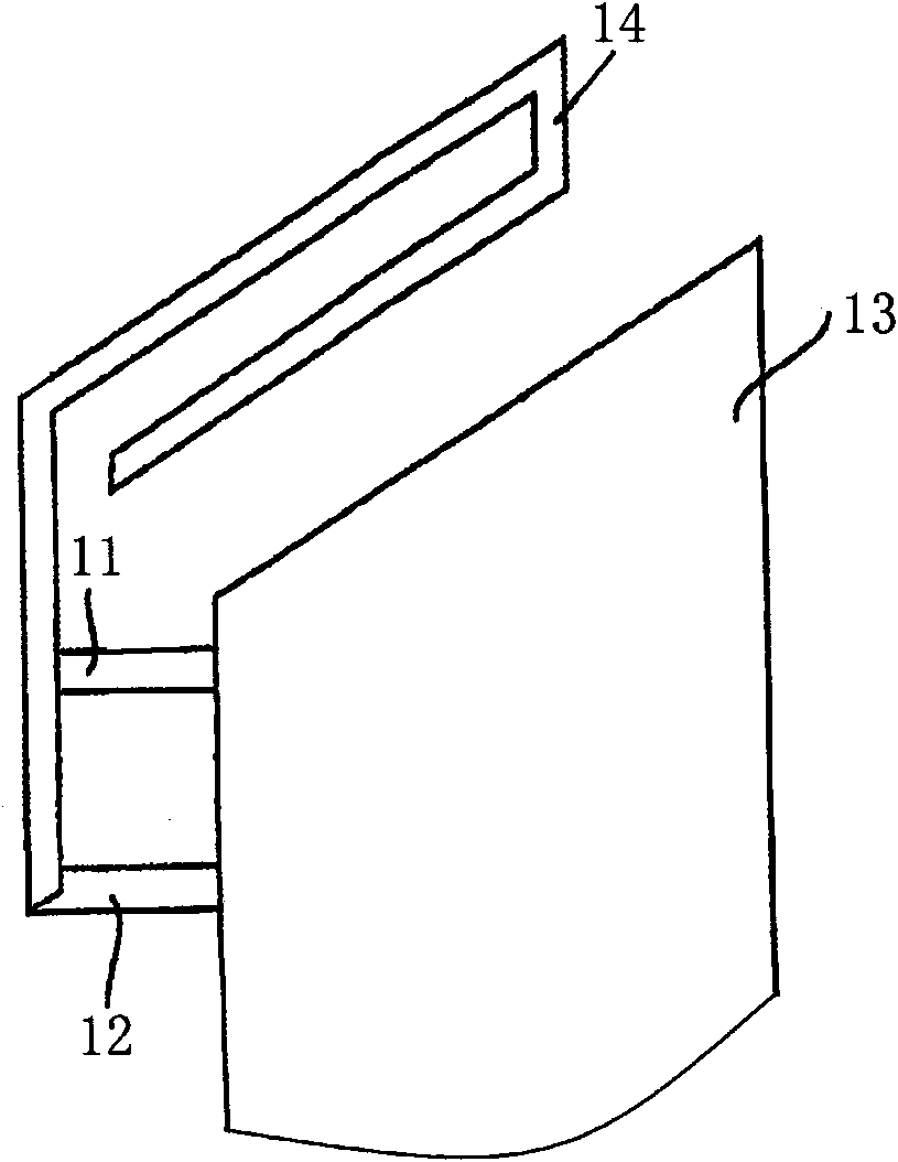
[0027] The design principle and basic structure of the Planar Inverted-F (PIFA, Radiation of Planar Inverted-F Antenna) antenna are introduced below. Fig. 1 is a schematic diagram of the principle structure of a PIFA antenna arranged in a mobile terminal. As shown in Fig. 1, the PIFA antenna includes a feeder 14 and a feeder panel 13. For a m...


PUM


Abstract

The invention discloses a method for improving radiation performance of an antenna. A mobile terminal is provided with a conducting piece; the conducting piece on the mobile terminal is used as a feeder line of the antenna of the mobile terminal; the conducting piece is used as a feeder line of the antenna of the mobile terminal; and the length of the feeder line is more than 90mm. The invention discloses the mobile terminal simultaneously; a mobile terminal body is provided with the conducting piece which is used as the feeder line of the mobile terminal antenna, and the length of the feeder line is more than 90mm; and the feeder line is respectively connected with a feeding point or a feeding lead of the mobile terminal antenna and an earthing point or an earthing lead of the mobile terminal antenna. In the invention, a metal piece arranged a mobile terminal machine body can not cause any influence to the antenna of the mobile terminal, and ensure the radiation performance of the antenna of the mobile terminal. The technical scheme of the invention is simple and practical.

Description

technical field [0001] The invention relates to antenna radiation technology, in particular to a method for improving antenna radiation performance and a mobile terminal. Background technique [0002] With the rapid development of mobile communication terminals, in addition to meeting the basic call functions, people have more and more requirements for the appearance of mobile terminals, and the design of mobile terminals is becoming more and more pleasing to the eye. More and more metal trim pieces. Although the mobile terminal is decorated, these metal decorations often affect the performance of the antenna of the mobile terminal, especially the low-frequency antenna. The performance is greatly affected by the metal decoration, which increases the difficulty of antenna debugging. At present, mobile terminals support many frequency bands. For the current mainstream WCDMA (Wideband Code Division Multiple Access) mobile terminals, there are generally 7 frequency bands, inclu...

Claims


Application Information

Patent Timeline
Patent Type & Authority Applications(China)
IPC IPC(8): H01Q1/24H04B1/40
CPCH01Q1/243H01Q9/42H01Q1/38H01Q9/0421
Inventor 刘锋昱于小军
Owner ZTE CORP
Learn More