No-load applied voltage test and protection method for DC ice-smelting device
A no-load pressure test, DC ice melting technology, applied in the direction of measurement device, overhead installation, cable installation, etc., can solve the problems of less than 5% annual utilization rate and less time.
Inactive Publication Date: 2010-08-25
ELECTRIC POWER RESEARCH INSTITUTE, CHINA SOUTHERN POWER GRID CO LTD
View PDF3 Cites 8 Cited by
- Summary
- Abstract
- Description
- Claims
- Application Information
AI Technical Summary
Problems solved by technology
The DC deicing device operates in the deicing condition for very little time each year, and the annual utilization rate is less than 5%.
Method used
View moreImage
Smart ImageViewing Examples
Examples
Embodiment 1
Embodiment 2
Login to View More PUM
 Abstract
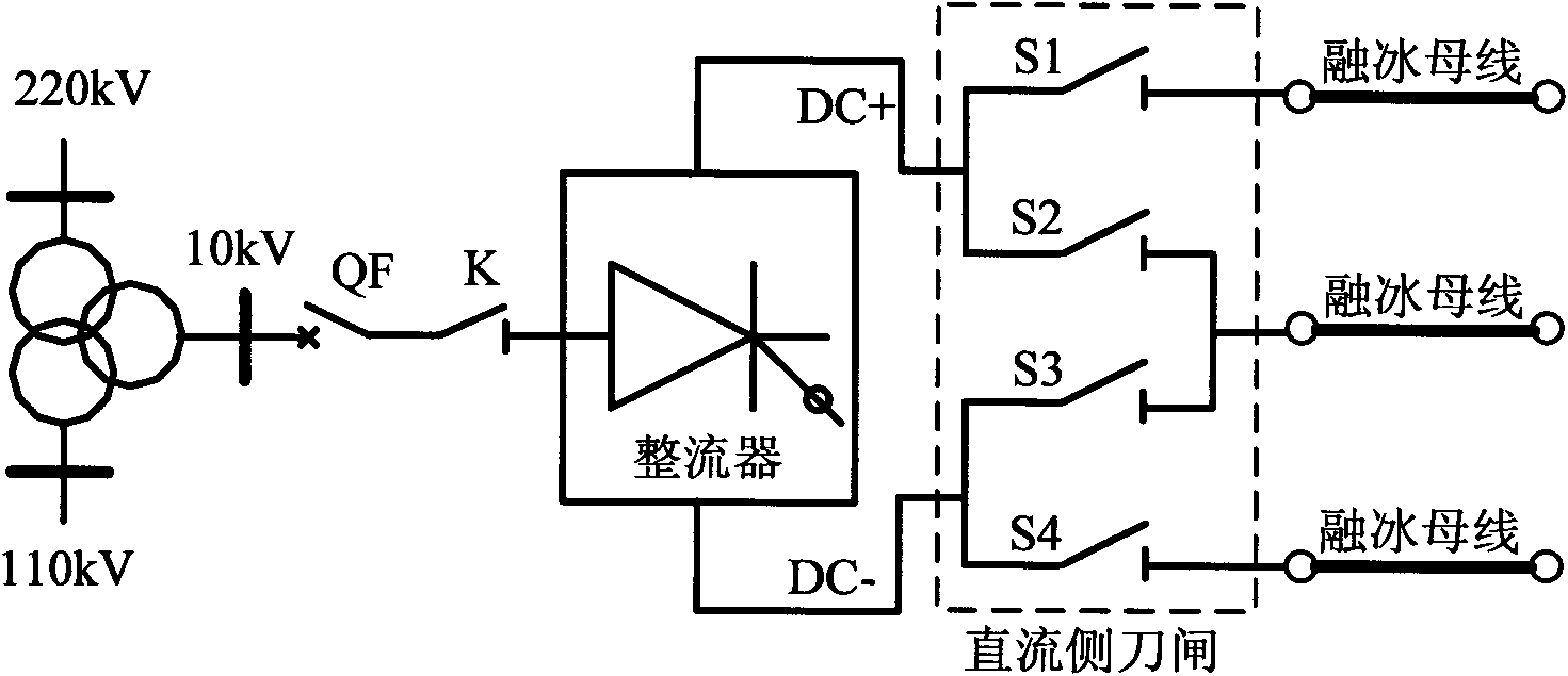
The invention discloses a no-load applied voltage test and protection method for a DC ice-smelting device. The method comprises the following steps of: 1) connecting the DC ice-smelting device with an ice-smelting bus; 2) opening the circuit on the DC side, and turning on a power switch of the DC ice-smelting device; 3) setting a DC voltage reference value of the open circuit test of the circuit, sending a command for beginning the no-load applied voltage test out, performing linear change on the DC voltage at the preset speed, and maintaining a certain time; and 4) determining no abnormality, stopping the no-load applied voltage test, and locking a converter valve. Due to the adoption of the applied voltage test and protection method, the DC voltage endurance capacity of the converter valve, a DC side disconnecting link and the ice-smelting bus can be checked under the condition of not connecting the DC circuit, the triggering capacity of the converter valve is checked, the control function of the control and protection system is checked, and the DC ice-smelting device can be reliably operated when the ice needs to melt. The no-load applied voltage test and protection method for the DC ice-smelting device are convenient and practical.
Description
No-load pressurization test and protection method of a DC deicing device technical field The invention relates to a no-load pressurization test and a protection method of a direct current deicing device, which belongs to the transformation technology of the no-load pressurization test and protection method of a direct current deicing device. Background technique Icing of transmission lines in winter seriously threatens the safe operation of the power system. The successful development of the DC ice melting device has played a huge role in improving the power grid's ability to resist ice disasters. The DC deicing device mainly has two types with a dedicated rectifier transformer and without a dedicated rectifier transformer, and it can be determined whether to configure a static var compensation device (SVC) function according to the needs of the system at the place of use. Due to the task of power transmission, the transmission line can be stopped and connected to the ic...
Claims
Login to View More Application Information
Patent Timeline
 Patent Type & Authority Applications(China)
IPC IPC(8): G01R31/00G01R31/12H02G7/16
Inventor 傅闯黎小林饶宏许树楷赵杰李立浧吴怡敏
Owner ELECTRIC POWER RESEARCH INSTITUTE, CHINA SOUTHERN POWER GRID CO LTD
- R&D Engineer
- R&D Manager
- IP Professional
- Industry Leading Data Capabilities
- Powerful AI technology
- Patent DNA Extraction
Learn More Browse by: Latest US Patents, China's latest patents, Technical Efficacy Thesaurus, Application Domain, Technology Topic, Popular Technical Reports.
© 2024 PatSnap. All rights reserved.Legal|Privacy policy|Modern Slavery Act Transparency Statement|Sitemap|About US| Contact US: help@patsnap.com


