Automobile engine nacelle curb girder front part with reinforced energy absorbing structure

A technology for engine compartments and energy-absorbing structures, applied in substructures, vehicle components, transportation and packaging, etc., can solve the problems of bending energy absorption, insufficient energy absorption, and increased costs, and achieve the effect of easy stamping and reasonable block division

Active Publication Date: 2010-08-25
CHONGQING CHANGAN AUTOMOBILE CO LTD
View PDF9 Cites 6 Cited by
  • Summary
  • Abstract
  • Description
  • Claims
  • Application Information

AI Technical Summary

Problems solved by technology

[0004] Figure 2 is the front section of another automobile engine compartment side beam, which is welded by the front body, the front panel of the outer sealing plate and the front collision inner box, and the front section of the engine compartment side beam is made of three sections of different thicknesses: front, middle and rear The material is made of laser tailor welding, and the front, middle and rear sections are all high-strength steel plates, which is not only unreasonable to divide into blocks, but also greatly increases the cost; when a low-speed collision occurs, it is inconvenient to maintain
[0005] The front section of the side beams of the engine compartment of the above two cars is not equipped with reinforcements, and only a small part is equipped with energy-absorbing structures, so that in the event of a collision, there will be bending phenomena and insufficient energy absorption, resulting in low scores in frontal collisions. , can not get the indicators stipulated by E-NCAP and C-NCAP

Method used


Image

  • Automobile engine nacelle curb girder front part with reinforced energy absorbing structure
  • Automobile engine nacelle curb girder front part with reinforced energy absorbing structure
  • Automobile engine nacelle curb girder front part with reinforced energy absorbing structure

Examples


Embodiment Construction

[0022] The present invention will be further described below in conjunction with the accompanying drawings.

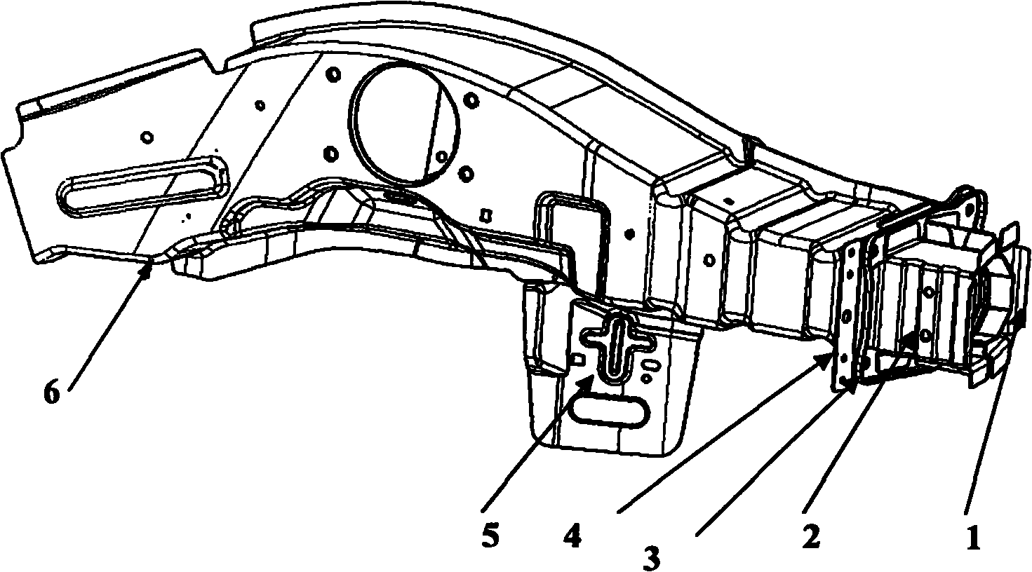
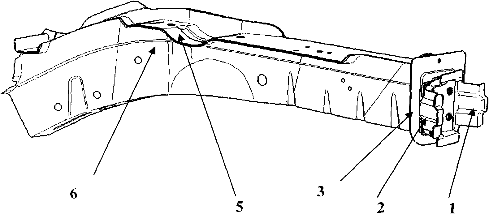
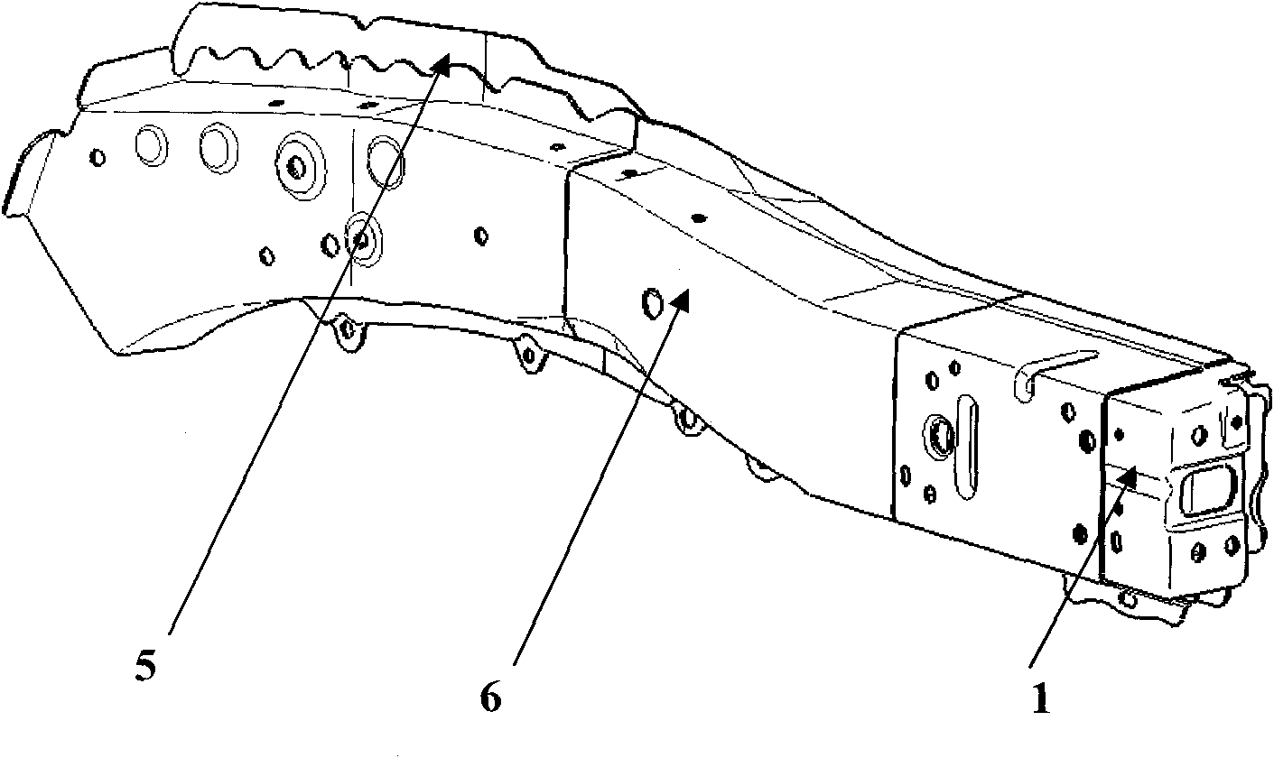
[0023] Referring to Fig. 3, Fig. 4, Fig. 5, Fig. 6, Fig. 7 and Fig. 8, a car engine compartment side beam front section with a reinforced energy-absorbing structure includes the front section body 6, and the front section of the outer sealing plate connected to the lower part of the front section body. Plate 5, the front lock plate 4 connected to the right end of the front section body, the front crash box support 3 connected to the front lock plate; one end of a front crash inner box 1 and a front crash outer box 2 are all connected to the front crash box support Seat 3 is connected, the front collision inner box is relatively buckled with the front collision outer box, and the front collision inner mouth box is located inside the mouth of the front collision outer box, forming a box-in-box structure to ensure sufficient energy absorption during offset collisions ; In...


PUM


Abstract

The invention discloses an automobile engine nacelle curb girder front part with a reinforced energy absorbing structure. The front part comprises a body, a foreplate of an external closing plate, a front lock plate, and a support of a front crush box, which is connected on the front lock plate. The invention is characterized in that one end of the front internal crush box and one end of the front external crush box are respectively connected with the support of the front crush box; the front internal crush box and the front external crush box are oppositely locked with each other and the front internal crush box is arranged inside the front external crush box; a first half reinforced cylinder and a second half reinforced cylinder are arranged inside the front internal crush box and are oppositely connected into a cylinder; and one end of the cylinder is connected with the support of the front crush box. Adopting a unique structure with the front internal crush box inside the front external crush box guarantees the complete absorption of energy during offset collision; the partitioning is reliable and punch forming is easy, thereby guaranteeing that an automobile can be successfully repaired when colliding at low speed; and the invention completely reaches the high-star score E-NCAP and C-NCAP according to the analysis of CAE.

Description

technical field [0001] The invention relates to automobile parts, in particular to a front section of an automobile engine compartment side beam with a reinforced energy-absorbing structure. Background technique [0002] Today, the automobile industry is in the fastest growing period in history, the number of automobiles has increased substantially, and traffic accidents have also increased year by year. As people pay more attention to life, whether at home or abroad, the star rating of car collisions has become an important factor for people to consider when buying a car. And in order to make self-owned brand cars enter foreign markets, they must get high scores in E-NCAP (European Automobile Evaluation Specification), but the bias of E-NCAP (64km / h) is the difficulty of scoring, because it is far higher It is based on the domestic C-NCAP (China Automobile Evaluation Specification) (56km / h). [0003] Figure 1 is a front section of the side beam of an automobile engine com...

Claims


Application Information

Patent Timeline
Patent Type & Authority Applications(China)
IPC IPC(8): B62D21/15
Inventor 邹途祥王珂邵金华
Owner CHONGQING CHANGAN AUTOMOBILE CO LTD
Why Eureka
Try Eureka