Powerless constant length cable traction mechanism

A technology of cable traction and power, which is applied in the direction of cable arrangement between relative moving parts, cable installation, electrical components, etc. It can solve the problems of unsuitable optical cables and affecting the life of cables, so as to save cable length and facilitate track Length, easy to change effect

Inactive Publication Date: 2010-08-18
ENG DESIGN & RES INST OF GENERAL ARMAMENTS DEPT
View PDF0 Cites 4 Cited by
  • Summary
  • Abstract
  • Description
  • Claims
  • Application Information

AI Technical Summary

Problems solved by technology

This method requires a set of motor, speed reduction and control mechanism
At the same time, since the retracted cables are all wound on the reel, repeated bending will affect the life of the cables; a slip ring connection is required in the mechanism, and for some cables that cannot be disconnected and connected to the slip ring, such as optical cables Be applicable

Method used


Image

  • Powerless constant length cable traction mechanism
  • Powerless constant length cable traction mechanism
  • Powerless constant length cable traction mechanism

Examples


Embodiment Construction

[0015] The present invention will be further described below in conjunction with the accompanying drawings.

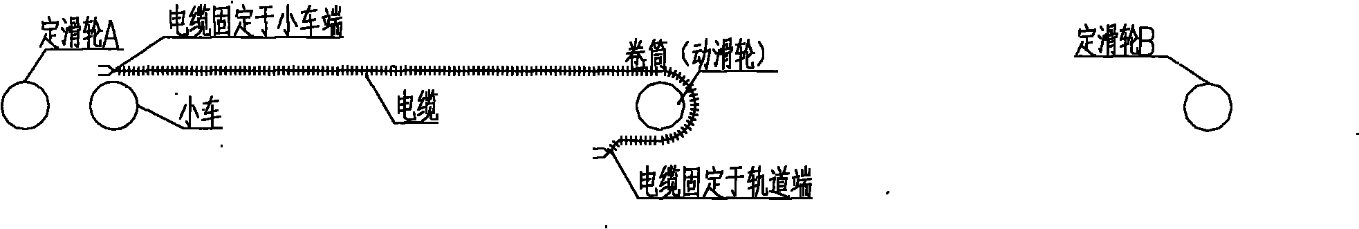
[0016] figure 1 It is the layout diagram of trolley, winding reel (moving pulley), fixed pulley relative to the track. Among them, the fixed pulley is fixed at both ends of the track, and the trolley and the reel can move along the track. Through the layout of the traction line, the distance from the trolley to the fixed pulley B is twice the distance from the reel to the fixed pulley B, that is figure 1 The L in is variable, but the L on both sides of the reel remains equal.

[0017] figure 2 A schematic diagram of the cable setup is given, one end of the cable is fixed in the middle of the track, and the other end is fixed on the trolley. The function of the reel is to guide the cable to change direction, and the radius of the wheel guiding the cable by the reel is determined according to the bending radius of the selected cable. From figure 2 It can be seen t...


PUM


Abstract

The invention discloses a powerless constant length cable traction mechanism, which comprises a trolley arranged on a rail, a winding reel and two fixed pulleys fixed at two ends of the rail. One end of a cable moves around the winding reel and is fixed in the middle of the rail, and the other end of the cable is fixed on the trolley, wherein the winding reel is used for guiding the cable to change the direction; a pulling cable with one end fixed at an end of the rail moves around the winding reel to return to a fixed pulley A at the same end of the rail, moves around the fixed pulley A to return to the other fixed pulley B opposite to the fixed pulley A, moves around the fixed pulley B to return to the winding reel again, and moves around the winding reel again to return and be fixed to the other end of the rail; the two ends of the traction cable passing through the trolley are fixed on the trolley respectively; a driving device is arranged on the trolley, so that the trolley can move along the rail; and the winding reel moves on the rail at a speed half of that of the trolley. Additional power is not required according to the invention; the reel is driven to move by using the traction cable when the trolley moves; the length of the cable is saved; and the motion part can be replaced conveniently.

Description

technical field [0001] The invention belongs to the field of mechanical traction, and in particular relates to a non-powered constant-length cable traction mechanism. The mechanism uses a pulley block organization and cable winding to provide cable connections for the movable parts of the track-running mechanism. Background technique [0002] At present, the short-distance cable guide methods mainly include the chain sleeve method and the elevator hoisting cable method. Among them, the cable guide device adopting the chain sleeve method uses multiple monomers similar to the chain sleeve to connect through pivot pins to ensure mutual contact. Rotation angle ≯180°. However, the disadvantage of this device is that if the distance of the cable is long, when the operating mechanism is at one end, there will be a large number of monomers with openings downward, which will lead to heavy weight and uneven stress on the monomers. Therefore this mechanism is only applicable to the si...

Claims


Application Information

Patent Timeline
IPC IPC(8): H02G11/00
Inventor 刘松诸方舟卢连成宋道宏郑明强
Owner ENG DESIGN & RES INST OF GENERAL ARMAMENTS DEPT
Why Eureka
Try Eureka