Eureka AIR delivers breakthrough ideas for toughest innovation challenges, trusted by R&D personnel around the world.

Method for establishing local exchange, core network equipment and base station subsystem

A technology of base station subsystem and core network equipment, applied in the field of establishing local exchange, core network equipment and base station subsystem, can solve the problems of call quality and user experience, save execution time, improve user experience, and save messages effect of quantity

Active Publication Date: 2010-08-11
HUAWEI TECH CO LTD
View PDF0 Cites 6 Cited by
  • Summary
  • Abstract
  • Description
  • Claims
  • Application Information

AI Technical Summary

Problems solved by technology

Moreover, handover has a certain impact on the call quality, and local switching will also have a certain impact on the call quality. The superposition of the two adverse effects may seriously affect the user experience

Method used


Image

  • Method for establishing local exchange, core network equipment and base station subsystem
  • Method for establishing local exchange, core network equipment and base station subsystem
  • Method for establishing local exchange, core network equipment and base station subsystem

Examples


Embodiment 1

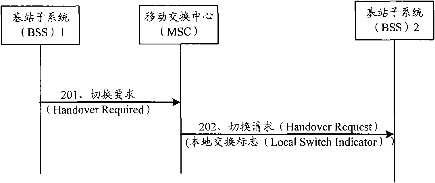
[0061] Embodiment 1. It is assumed that terminals MS1 and MS2 are involved in the handover process. Before the handover, MS1 is located at BSS1, and MS2 is located at BSS2; after the handover, both MS1 and MS2 are located at BSS2. refer to figure 2 , which is a signaling flow chart of embodiment 1 of method 1 for establishing local switching in the embodiment of the present invention, and the specific steps are as follows:

[0062] 201. BSS1 sends a Handover Required (Handover Required) message to the MSC;

[0063] 202. After the MSC judges that the handover is completed, the two calls corresponding to MS1 and MS2 will be located in BSS2 and when the two calls meet the conditions for local switching, send a handover request (HandoverRequest) message to BSS2, and the Handover Request message contains information The element is used to indicate that BSS2 establishes local switching after the handover succeeds.

[0064] The MSC can determine which calls can establish a local e...

Embodiment 2

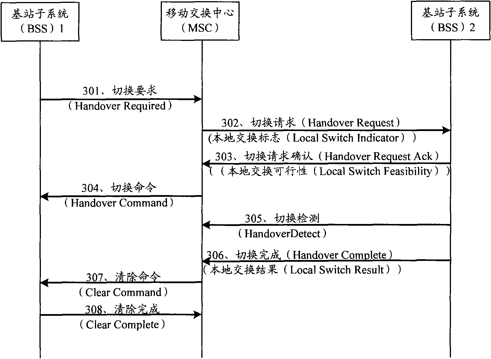
[0072] Embodiment 2. During inter-BSS handover process, refer to image 3 , is the signaling flow chart of Embodiment 2 of Method 1 for establishing local switching in the embodiment of the present invention. Before the handover, MS1 is located at BSS1, and MS2 is located at BSS2; after the handover, both MS1 and MS2 are located at BSS2. The difference from Embodiment 1 is that when local switching can be established, BSS2 will execute the local switching operation after the two calls that constitute the session are switched successfully, and use a certain information element in the switching completion message to notify The execution result of MSC local switching, and when the local switching of the two calls is successfully established by the MSC, the core network user plane resources allocated for the two calls are cleared. The specific process is described in detail below:

[0073] 301. BSS1 sends a Handover Required (Handover Required) message requiring handover to the MS...


PUM


Abstract

The invention discloses a method for establishing local exchange, core network equipment and a base station subsystem, wherein the method for establishing the local exchange comprises the following steps of: receiving a first message which is from a first base station subsystem and requests for switching; and determining that two calls forming a conversation after switching is finished are both positioned in a second base station subsystem according to the first message requesting for switching, sending a second message requesting for switching to the second base station subsystem when the condition of the local exchange is satisfied, and indicating the second base station subsystem to establish the local exchange for the two calls after the switching is succeeded. Because an additional flow for establishing the local exchange needs not to be added in the technical scheme of the invention, the local exchange is realized while switching, thereby saving the execution time of the flow and saving the message quantity of an A interface. Because a single flow is not needed for establishing the local exchange, an adverse influence on the conversation quality can not be generated due to the establishment of the local exchange, thereby improving the user experience.

Description

technical field [0001] The invention relates to the technical field of wireless communication, in particular to a method for establishing a local exchange, core network equipment and a base station subsystem. Background technique [0002] The transmission network is an important part of the wireless communication network. At present, operators in many countries and regions are affected by the bottleneck of the transmission resources connecting the wireless access network and the core network, which affects the deployment, operation and business development of the wireless network. In regions such as Africa, wireless networks are growing much faster than wired networks. In regions represented by Europe, due to the restrictions of local laws and regulations, the construction of ground cable transmission networks cannot be constructed according to the needs of operators. Even countries with abundant terrestrial transmission resources, such as China, still face the problems of ...

Claims


Application Information

Patent Timeline
Patent Type & Authority Applications(China)
IPC IPC(8): H04W36/08H04W76/02
CPCH04W36/00H04W36/0064
Inventor 朱星秦钧王之曦王超
Owner HUAWEI TECH CO LTD
Why Eureka
Eureka Blog
Learn More