Knitting needle bed swinging mechanism of warp knitting machine

A warp knitting machine and needle bed technology, which is applied to the field of swing motion mechanism, can solve the problems of difficult processing and manufacturing of cam mechanism, unsuitable high speed of cam mechanism, limiting the speed of warp knitting machine, etc., and achieves simple processing and manufacturing, and a wide range of travel speed ratio coefficients. , a variety of effects

Active Publication Date: 2010-08-11
临沂高新区金蓝领劳务有限公司
View PDF3 Cites 11 Cited by
  • Summary
  • Abstract
  • Description
  • Claims
  • Application Information

AI Technical Summary

Problems solved by technology

The transmission requirement of the travel speed ratio coefficient is about 2, which is relatively large. In order to realize the movement requirement, the knitting needle swing mechanism used on the warp knitting machine generally adopts a cam mechanism. Since the cam mechanism is not suitable for high speed, the speed of the warp knitting machine is limited. Further improvement, and the cam mechanism is difficult to manufacture and the cost is high

Method used


Image

  • Knitting needle bed swinging mechanism of warp knitting machine
  • Knitting needle bed swinging mechanism of warp knitting machine
  • Knitting needle bed swinging mechanism of warp knitting machine

Examples


Embodiment Construction

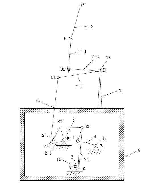
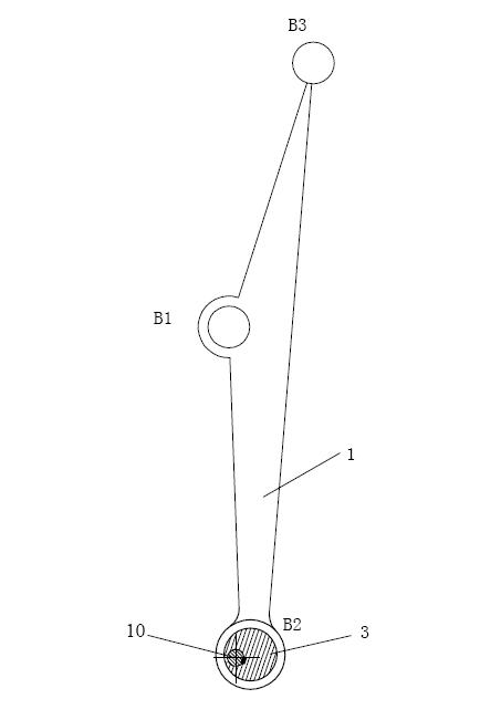
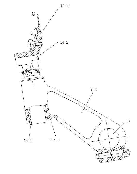
[0017] The embodiment shown in the drawings includes main shaft 10, No. 1 pin shaft 11, No. 2 pin shaft 12, pendulum shaft 13, No. 1 triangular member 1, No. 2 triangular member 2, No. 1 connecting rod 4, and No. 2 connecting rod 5. No. 3 connecting rod 6, and the needle bed 14-2 and the needle bed seat 14-1 supporting the needle bed 14-2. Described main shaft 10, No. 1 pin shaft 11, No. 2 pin shaft 12 are in the oil tank of warp knitting machine and are respectively supported by brackets. Described balance shaft 13 is supported by the support 9 that is fixed on the oil tank top of warp knitting machine. Main shaft 10, No. 1 long pin shaft 11, No. 2 long pin shaft 12 and balance shaft 13 are long shafts equal to the width of the machine. The No. 1 triangular member 1, the No. 2 triangular member 2, the No. 1 connecting rod 4, the No. 2 connecting rod 5, and the No. 3 connecting rod 6 are all arranged in the oil tank of the warp knitting machine. The above-mentioned No. 1 tri...


PUM


Abstract

The invention relates to a knitting needle bed swinging mechanism of a warp knitting machine, which is provided with a main shaft, a swinging shaft, a knitting needle bed and a knitting needle seat, wherein the knitting needle seat supports the knitting needle bed and is connected with a needle bed driven swinging arm in a moving pair way. In addition, the knitting needle bed swinging mechanism of a warp knitting machine is also provided with a pin shaft I, a pin shaft II, a triangular member I, a triangular member II, a connecting rod I, a connecting rod II and a connecting rod III, wherein an eccentric wheel is fixed to the main shaft; one end of the triangular member I is connected to the eccentric wheel in a rotating pair way, and other two ends of the triangular member I are respectively connected with the connecting rod I and the connecting rod II in the rotating pair way; the connecting rod I is connected with the pin shaft I in the rotating pair way; one end of the triangular member II is connected to the pin shaft II in the rotating pair way, and other two ends of the triangular member II are respectively connected with the connecting rod II and the connecting rod III in the rotating pair way; and the connecting rod III is connected with a needle bed drive swinging arm of a knitting needle bed assembly in the rotating pair way after penetrating through an oil tank. The invention is beneficial to improving the rotating speed of the whole machine, reduces the manufacture cost, and has wide realized travel speed variation coefficient range.

Description

technical field [0001] The invention relates to a warp knitting machine component, in particular to an oscillating motion mechanism of a warp knitting machine needle bed. Background technique [0002] In the process of weaving fabric by warp knitting machine, it is one of the important processes to form the fabric structure by taking the yarn from the hook of the knitting needle. In order to form the loop correctly, it is generally required to have the movement of the knitting needle, the movement of the bar and the settlement movement to cooperate with each other. . The movement of the bar is generally a swing around a fixed point. When the number of bars is small, its mass and moment of inertia are small, and the inertial force and moment of inertia generated during the swing have little influence on the speed of the machine. For a long time, its mass and moment of inertia are large. If it still swings, there will be a large inertial force and moment of inertia, which is ...

Claims


Application Information

Patent Timeline
IPC IPC(8): D04B27/08
Inventor 曹清林
Owner 临沂高新区金蓝领劳务有限公司
Why Eureka
Try Eureka