Partial energy coupled separation system of carbon 3, carbon 4 and carbon 5 used in predepropanization technological process and operation method

A technology for depropane ethylene and separation systems, which is applied in fractionation, gas mixture processing, petroleum industry and other directions to achieve the effect of reducing quantity, equipment investment and energy consumption

Inactive Publication Date: 2010-08-11
TIANJIN UNIV
View PDF54 Cites 16 Cited by
  • Summary
  • Abstract
  • Description
  • Claims
  • Application Information

AI Technical Summary

Problems solved by technology

The above-mentioned application of energy-coupled partition towers in the actual industrial ethylene process for product separation is only patent US6291734, which has an energy-coupled rectification design for the separation of C3, C4 and C5 in the ethylene process, but this process is only Partial Energy Coupled Distillation Column Using Indirect Separation Sequence Structure

Method used


Image

  • Partial energy coupled separation system of carbon 3, carbon 4 and carbon 5 used in predepropanization technological process and operation method
  • Partial energy coupled separation system of carbon 3, carbon 4 and carbon 5 used in predepropanization technological process and operation method
  • Partial energy coupled separation system of carbon 3, carbon 4 and carbon 5 used in predepropanization technological process and operation method

Examples


Embodiment 1

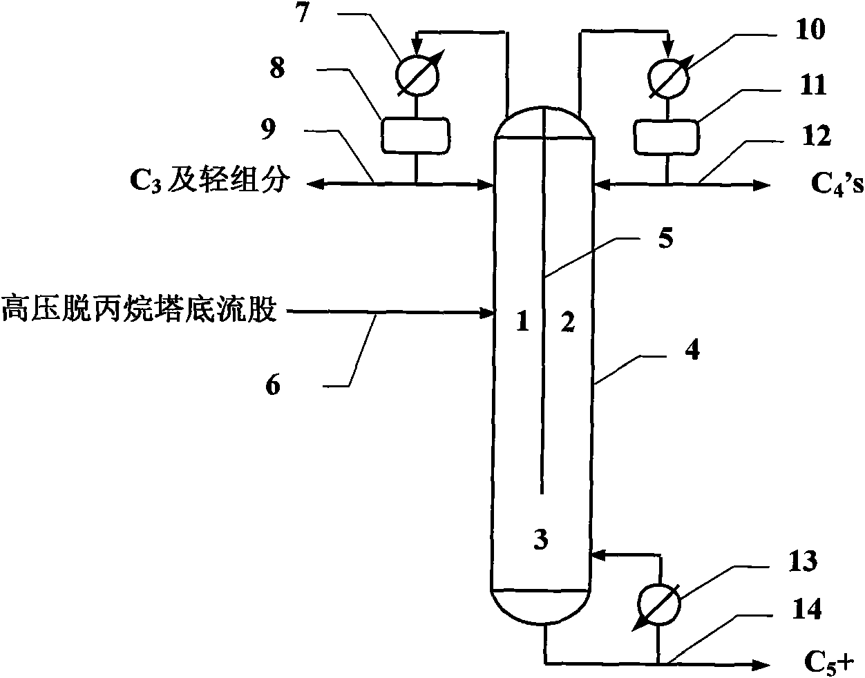
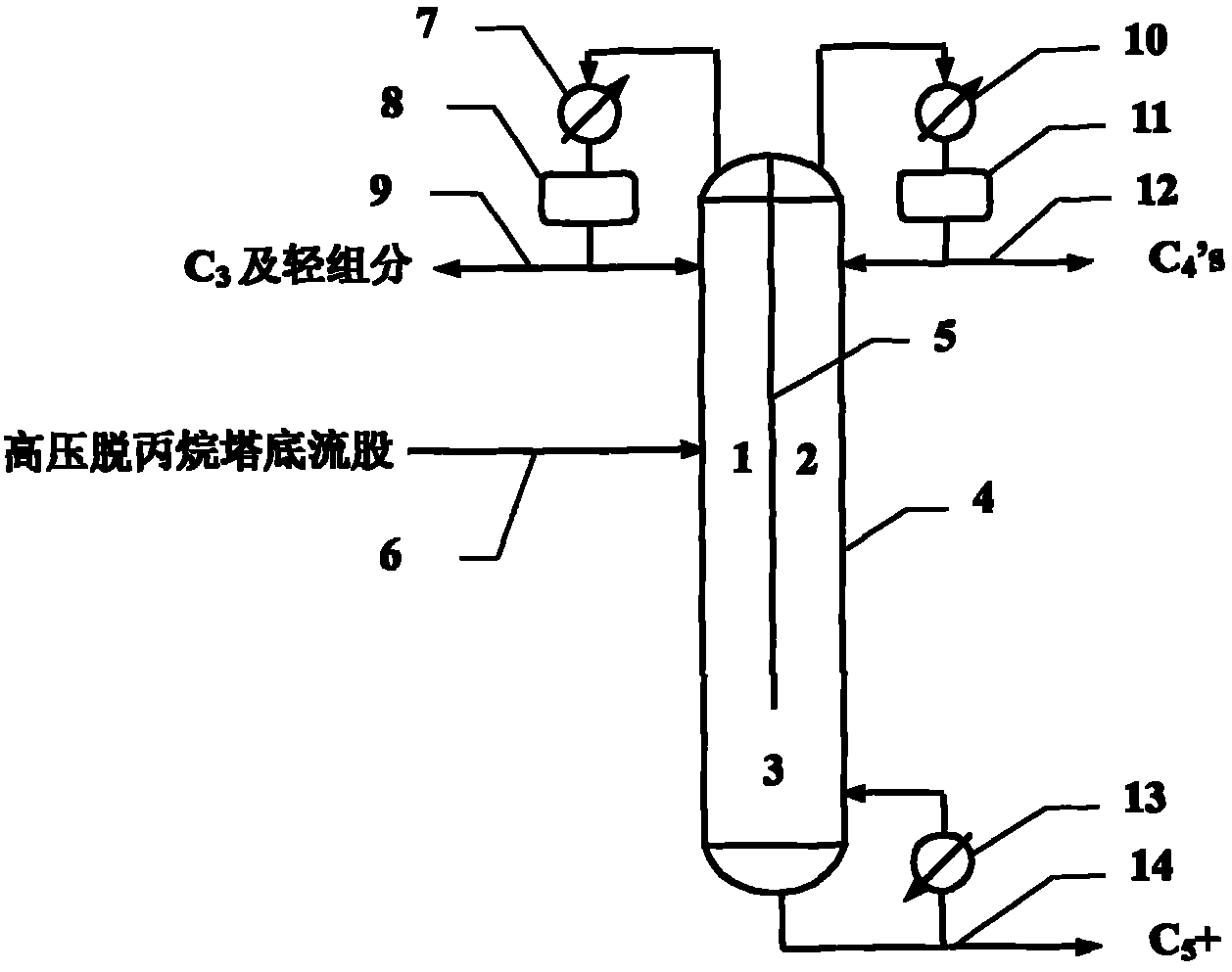
[0028] Embodiment 1: as figure 1 , the direct separation sequence structure part energy coupling partition column 4 is used for rectification and separation when the content of C3 in the raw material is relatively large, that is, the C in the raw material 3 The content is greater than that of C 4 and C 5+ Component content and raw material composition are shown in Table 1. The tower contains a vertical wall, that is, the partition 5 starts from the top of the tower to a certain tray in the tower, and divides the tower into three areas, area 1, area 2 and area 3. The raw material enters the feed plate from area 1 through the feed line 6, and area 1 mainly realizes C 3 and C 4 、C 5+ Separation between components, C 3 The fraction is extracted from the top of the zone 1 tower and enters the reflux tank 8 through the condenser 7, and a part is used as C 3 The product is withdrawn from pipeline 9, and another part is returned to zone 1 as reflux liquid. Separation by zone 1...

Embodiment 2

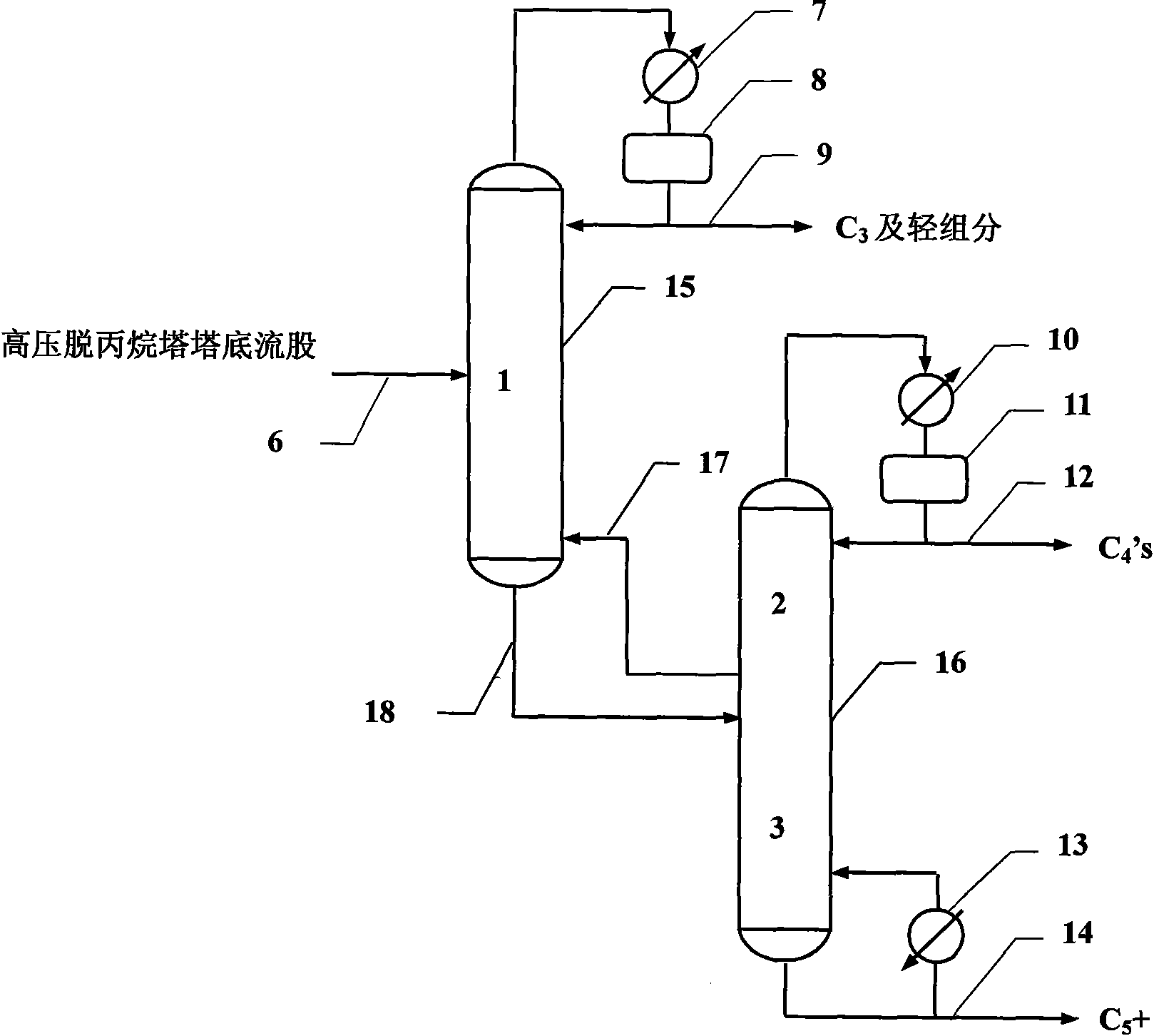
[0052] Embodiment 2: as figure 2 , a partially energy-coupled direct distillation column sequence, used for distillation and separation when the C3 content in the raw material is relatively high. The composition of the raw material is shown in Table 1. It includes two rectification towers, the first rectification tower 15 of the direct sequence and the second rectification tower 16 of the direct sequence. The separation process composed of these two columns is thermodynamically the same as figure 1 The direct separation sequence structure part energy coupling rectification tower 4 in the direct separation sequence is equivalent, and the region 1 corresponding to the tower 15 mainly realizes C 3 and C 4 、C 5+ The separation between the components, the zone 2 formed by the rectification section of the column 16 mainly realizes C 4 The rectification and separation of components, the zone 3 formed by the stripping section of tower 16 realizes C 5+ Stripping separation of com...


PUM

PropertyMeasurementUnit
heat loadaaaaaaaaaa

Abstract

The invention relates to a partial energy coupling separation system of carbon 3, carbon 4 and carbon 5 used in a predepropanization technological process and an operation method. Aiming at the situation that the content of C3 component is higher in raw materials, i.e., the content of the C3 component is respectively higher than that of C4 component and C5+ component, partial energy is integratedin a low pressure depropanizer and a debutanizer in the predepropanization technological process, and the partial energy coupled distillation column separation of a direct sequence structure can be completed in a diving wall column, or the separation is completed through the thermodynamically equivalent partial energy coupled direct distillation column sequence, thereby reducing the number of heat exchangers in the technological process, and obviously reducing the equipment investment and energy consumption in the separation process of a mixture.

Description

technical field [0001] The invention relates to the technical field of rectification, in particular to an energy coupling separation device and separation method for carbon three, carbon four and carbon five in the pre-depropane ethylene process, which can realize carbon three, carbon four and carbon five components Completing the separation in a rectification column or sequence of rectification columns with partial energy coupling can significantly reduce the equipment investment and energy consumption of the mixture separation process. Background technique [0002] In the production process of the former depropanization ethylene process (G.M.Clancy and R.W.Townsend, Ethylene Plant Fractionation, Chemical Engineering Progress, 1971, 67 (2): 41-44), the cracked gas is quenched, compressed, alkaline washed, dried, and then After cryogenically entering the high-pressure depropanizer, ethane and lighter components are separated from other heavy components in the stripping secti...

Claims


Application Information

Patent Timeline
Patent Type & Authority Applications(China)
IPC IPC(8): C10G70/04B01D3/14
Inventor 罗祎青袁希钢龚超余爱平
Owner TIANJIN UNIV
Why Eureka
Try Eureka