Foil bearing device
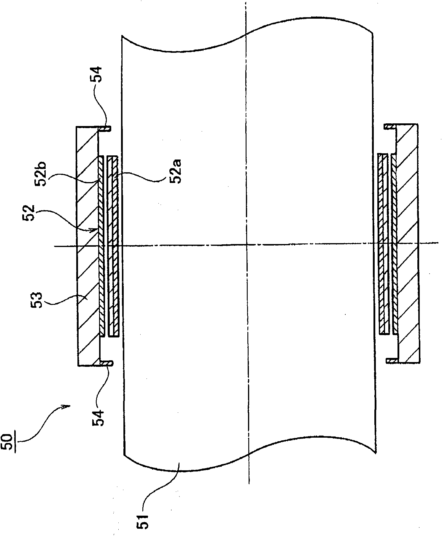
A technology of foil bearings and foil strips, applied to bearings, shafts and bearings, sliding contact bearings, etc., can solve the problems of bearing dysfunction, increased friction resistance of bearing parts, damage to rotating shaft 51, etc., and achieve good assembly workability , Good replacement workability and low replacement cost
- Summary
- Abstract
- Description
- Claims
- Application Information
AI Technical Summary
Problems solved by technology
Method used
Image

Examples
no. 1 approach
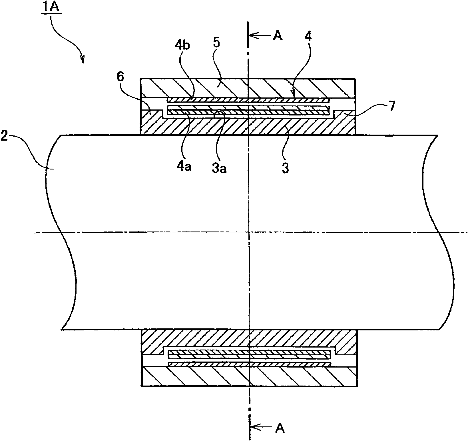
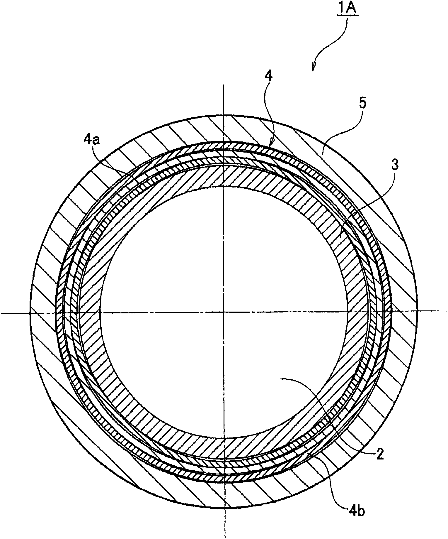
[0028] figure 2 and image 3 Representing the first embodiment of the present invention, figure 2 is a sectional view of the foil bearing device, image 3 Yes figure 2 A-A line sectional view.
[0029] like figure 2 and image 3 As shown, the foil bearing device 1A includes a rotating shaft 2 that is rotated at a high speed by a drive mechanism (not shown), a bearing inner ring 3 press-fitted into the outer circumference of the rotating shaft 2 , and a foil strip 4 arranged on the outer circumference of the bearing inner ring 3 . , and a bearing outer ring 5 arranged on the outer circumference of the foil strip 4 .
[0030] The bearing inner ring 3 has an outer peripheral surface 3a on which the inner peripheral side 4a of the foil strip 4 abuts, and a pair of foil strip displacement restricting portions 6 and 7 protruding from the outer peripheral surface 3a to the outer peripheral side.
[0031] The width dimension between the pair of foil tape displacement restrictin...
no. 2 approach
[0040] Figure 4 It is a cross-sectional view of a foil bearing device according to a second embodiment of the present invention.
[0041] like Figure 4 As shown, the foil bearing device 1B includes a rotating shaft 10 that is rotated at a high speed by a drive mechanism (not shown), a bearing inner ring 11 press-fitted into the outer circumference of the rotating shaft 10 , and a foil strip 4 arranged on the outer circumference of the bearing inner ring 11 . , and a bearing outer ring 5 arranged on the outer circumference of the foil strip 4 .
[0042] The rotary shaft 10 is formed as a step shaft composed of a small diameter portion 10a and a large diameter portion 10b. A stepped surface 10c is formed on the boundary between the small diameter portion 10a and the large diameter portion 10b.
[0043] The bearing inner ring 11 is press-fitted into the small diameter portion 10 a of the rotary shaft 10 . The bearing inner ring 11 has an outer peripheral surface 11a against...
no. 3 approach
[0052] Figure 5 It is a cross-sectional view of a foil bearing device according to a third embodiment of the present invention.
[0053] like Figure 5 As shown, the foil bearing device 1C includes a rotating shaft 20 that is rotated at high speed by a drive mechanism (not shown), a foil 4 arranged on the outer circumference of the rotating shaft 20 , and a bearing outer ring 5 provided on the outer circumference of the foil 4 . .
[0054] The rotating shaft 20 is formed as a grooved shaft composed of a small diameter portion 20a and a large diameter portion 20b. Step surfaces 20c and 20c are formed on the boundary between the small diameter portion 20a and the large diameter portion 20b, respectively.
[0055] The foil strip 4 is arranged on the outer periphery of the small diameter portion 20 a of the rotating shaft 20 . In this way, the large-diameter portions 20b and 20b of the rotating shaft 20 are arranged on the outer sides of both ends of the foil tape 4, respecti...
PUM
 Abstract
Description
Claims
Application Information
 - R&D
- Intellectual Property
- Life Sciences
- Materials
- Tech Scout
- Unparalleled Data Quality
- Higher Quality Content
- 60% Fewer Hallucinations
Browse by: Latest US Patents, China's latest patents, Technical Efficacy Thesaurus, Application Domain, Technology Topic, Popular Technical Reports.
© 2025 PatSnap. All rights reserved.Legal|Privacy policy|Modern Slavery Act Transparency Statement|Sitemap|About US| Contact US: help@patsnap.com