Piezoelectric type six-dimensional force sensor with adjustable load sharing ratio and test method thereof
A six-dimensional force sensor, electric technology, applied in the measurement of fluid pressure, measuring fluid pressure through electromagnetic components, instruments, etc., can solve the problem that the six-dimensional force sensor cannot adapt to variable-range six-dimensional force measurement, etc., to achieve simple structure and manufacturability Good, good stability
- Summary
- Abstract
- Description
- Claims
- Application Information
AI Technical Summary
Problems solved by technology
Method used
Image
Examples
Embodiment 1
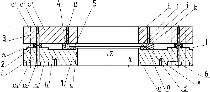
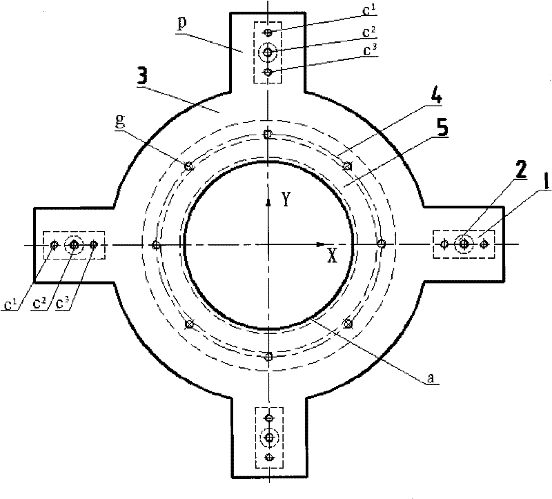
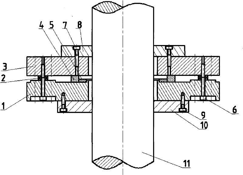
[0020]Example 1: The diameter of the measured shaft is 1000mm, the axial force is 1000000N, and the lateral force is 100000N. According to the force range allowed by the force sensor and considering the safety factor, the appropriate load sharing ratio is determined to be 0.5%, and a series of modularization is selected. The load sharing ring 4 and the positioning ring 5 are the largest set of load sharing, and the force sensitive element 2 is installed in the first through hole c of the lower body 1 , select a set of fixtures with an inner diameter of 1000mm and sufficient clamping force, and then install the positioning ring 5, the load sharing ring 4, and the force sensor 2 in sequence, and ensure that the upper surface e of the force sensor is on the surface of the load sharing ring by grinding. The surface k is at the same height, and the upper cover 3, the force sensitive element 2, and the lower body 1 are passed through the first through hole c of the lower body with th...
Embodiment 2
[0021] Example 2: When the measured shaft diameter is 100mm, the axial force is 100N, and the lateral force is 100N, the appropriate load sharing ratio is calculated to be 50%. Because the shaft is under less force, no load sharing ring is needed. 4 load sharing, and in order to improve the sensitivity of the sensor, the installation position of the force sensor 2 is selected as the third through hole c of the lower body 3 , that is, the position closest to the measured shaft 11, and a set of fixtures with an inner diameter of 100 mm are used, and then four force-sensitive elements 2 are installed in the third through hole c of the lower body 3 place, and use the pre-tightening screw 6 to pass the upper cover 3, the force sensitive element 2, and the lower body 1 through the third through hole c of the lower body 3 , the third threaded hole c on the upper cover 3 connection, wherein the pre-tightening force of the pre-tightening screw is 12000N, then the upper cover 3 is rigi...
PUM
 Abstract
Description
Claims
Application Information
 - R&D Engineer
- R&D Manager
- IP Professional
- Industry Leading Data Capabilities
- Powerful AI technology
- Patent DNA Extraction
Browse by: Latest US Patents, China's latest patents, Technical Efficacy Thesaurus, Application Domain, Technology Topic, Popular Technical Reports.
© 2024 PatSnap. All rights reserved.Legal|Privacy policy|Modern Slavery Act Transparency Statement|Sitemap|About US| Contact US: help@patsnap.com


