
Arc time inductor and electrical life on-line monitoring system of circuit breaker

An arcing time and circuit breaker technology is applied in the field of electric equipment detection devices, which can solve the problems of large dispersion of auxiliary contacts, large calculation and analysis errors, and difficulty in ensuring detection accuracy, and achieves good safety isolation performance and low insulation cost. , the effect of simple structure

Inactive Publication Date: 2010-07-28
GUILIN UNIV OF ELECTRONIC TECH
View PDF0 Cites 17 Cited by
  • Summary
  • Abstract
  • Description
  • Claims
  • Application Information

AI Technical Summary

Problems solved by technology

The above method can reflect the status and development trend of the electrical wear of the circuit breaker, but two problems must be solved first: ① the current collection problem; ② the determination of the arcing time and arcing time
As for the second question, in the past, the auxiliary contact was used as the signal of the starting point of arcing, but the auxiliary contact was very dispersed, and it was not synchronized with the starting point of arcing, which brought calculation and analysis errors to the monitoring system host Very large, it is difficult to ensure the detection accuracy requirements, and the general auxiliary contact can only be used as a reference signal

Method used


Image

  • Arc time inductor and electrical life on-line monitoring system of circuit breaker
  • Arc time inductor and electrical life on-line monitoring system of circuit breaker
  • Arc time inductor and electrical life on-line monitoring system of circuit breaker

Examples


Embodiment Construction

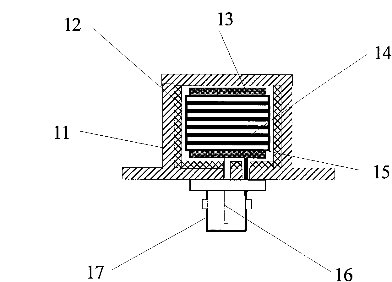
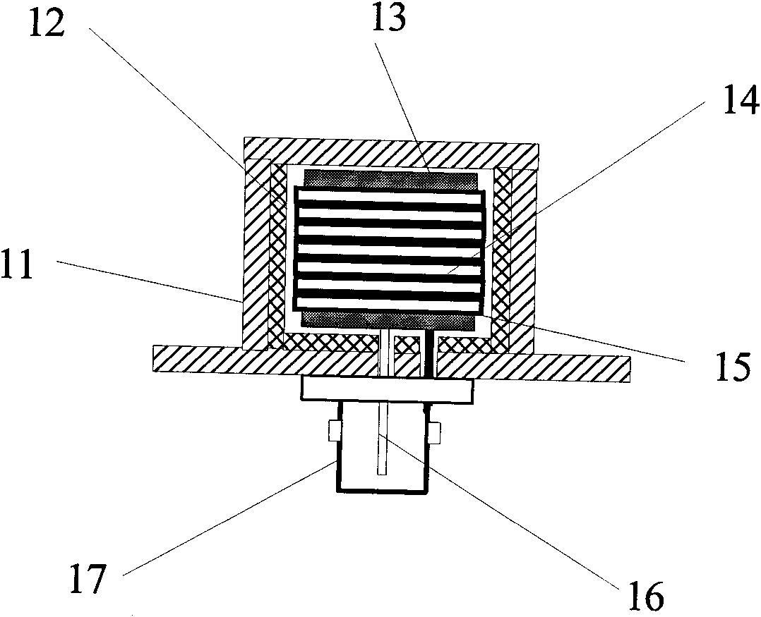
[0020] A circuit breaker arcing time sensor of the present invention such as figure 1 As shown, the principle of electromagnetic induction is adopted, and it is mainly composed of an insulating shell, an electromagnetic shielding layer, a magnetic core and a metal induction coil arranged in the insulating shell. A cylindrical magnetic core is located in the center of the insulating housing to increase the sensitivity of the circuit breaker arcing time sensor to electromagnetic field changes and pickup. The metal induction coil spirally surrounds the periphery of the magnetic core. It is the main functional component of the circuit breaker arcing time sensor to detect the initial arcing time and arcing time of the arc. It is used to receive and identify the characteristics of the spatial electromagnetic field change caused by the breaking arc. . The two ends of the metal induction coil protrude out of the insulating casing respectively as two output ends. In order to reduce t...


PUM


Abstract

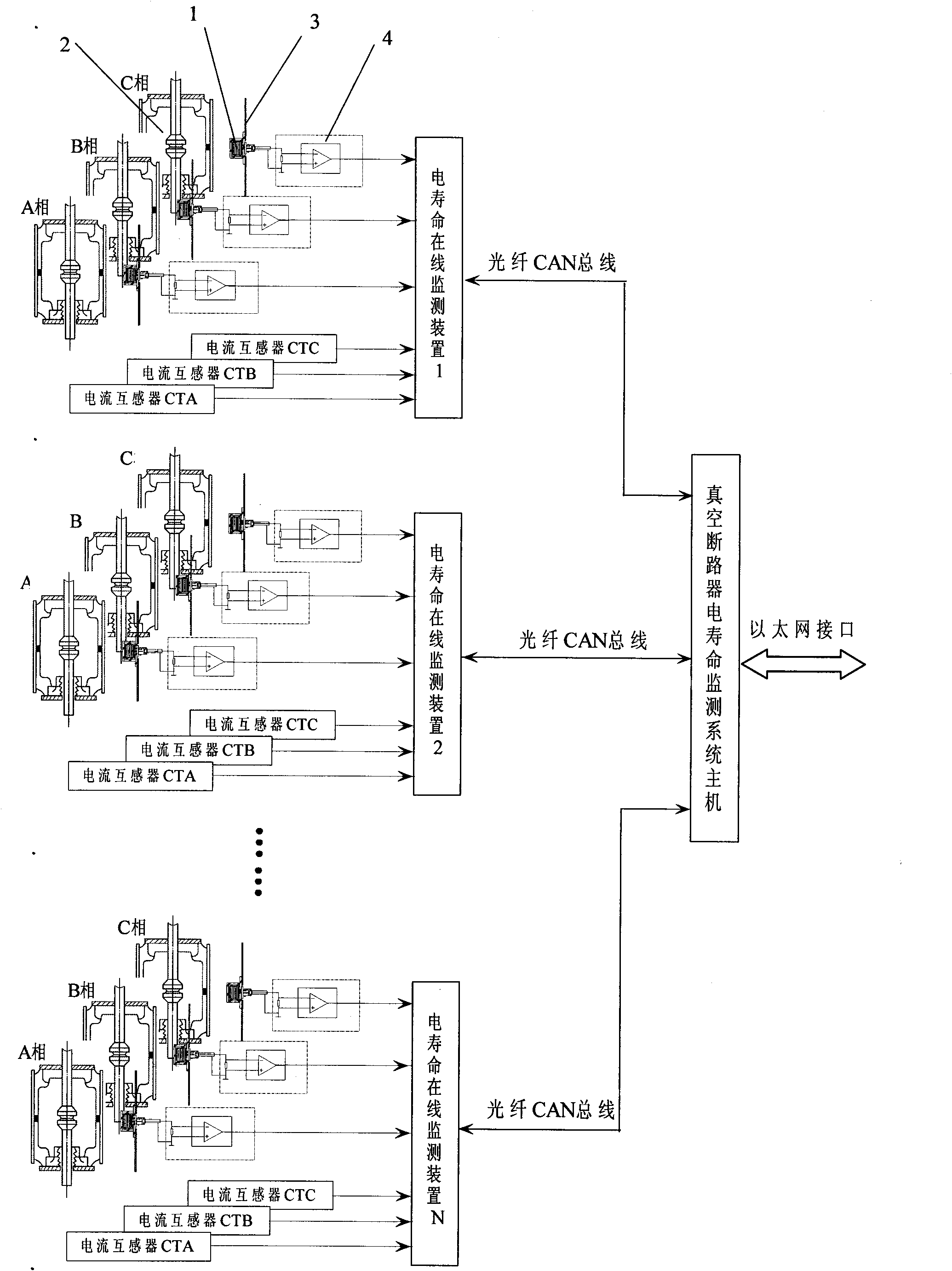
The invention discloses an arc time inductor and an electrical life on-line monitoring system of a circuit breaker, wherein the arc time inductor of the circuit breaker mainly comprises an insulating shell, an electromagnetic shielding layer, a magnetic core and a metal induction coil, wherein the electromagnetic shielding layer, the magnetic core and the metal induction coil are arranged in the insulating shell; the electromagnetic shielding layer is attached to the side wall and the inner side of the rear end surface of the insulating shell; the cylindrical magnetic core is positioned in the center of the insulating shell; the metal induction coil spirally encircles on the periphery of the magnetic core, and both ends of the metal induction coil respectively extend out of the insulating shell to be used as two output ends. The arc time inductor of the circuit breaker is arranged near an arc extinguish chamber of the circuit breaker, the front end of the arc time inductor is opposite to a detected contact, and the output end of the arc time inductor of the circuit breaker is connected to a mainframe of the monitoring system. The invention can accurately determine the initial arc time and the arc duration in the on-off process of the circuit breaker so as to ensure the electrical life on-line monitoring and the comprehensive judgment accuracy of the circuit breaker.

Description

technical field [0001] The invention relates to a power equipment detection device, in particular to a circuit breaker arcing time sensor and a circuit breaker electric life online monitoring system. Background technique [0002] The circuit breaker is the safety guard in the power system, which plays a dual role of control and protection in the system. With the transformation of electrical appliances and maintenance systems, the maintenance system of circuit breakers is developing from planned maintenance to condition-based maintenance. The condition of the circuit breaker contact system is related to the performance of breaking and closing short-circuit current of the circuit breaker. From the perspective of cumulative electrical wear, when other conditions are constant, the electrical wear of a circuit breaker is mainly determined by the arc energy. Therefore, the method of cumulative breaking current or cumulative arc energy is currently used to evaluate the electrical ...

Claims


Application Information

Patent Timeline
IPC IPC(8): G01R31/327
Inventor 范兴明张鑫李静黄知超唐专敏贺家敏
Owner GUILIN UNIV OF ELECTRONIC TECH
Learn More