
Measuring method of up-conversion intermediate energy level lifetime of erbium ions

A measurement method, the technology of erbium ions, applied in the direction of material excitation analysis, fluorescence/phosphorescence, etc., can solve the problems of complex testing process, difficult detection, expensive infrared detectors, etc., and achieve the effect of simple measurement process

Inactive Publication Date: 2011-07-27
HARBIN INST OF TECH
View PDF0 Cites 0 Cited by
  • Summary
  • Abstract
  • Description
  • Claims
  • Application Information

AI Technical Summary

Problems solved by technology

[0003] The present invention aims to solve the problems that the existing methods for measuring the infrared fluorescence lifetime require expensive infrared detectors, the testing process is complicated, the delay between two beams needs to be introduced, and the detection is difficult, and a kind of erbium ion is provided. Measuring Method of Upconversion Intermediate Energy Level Lifetime

Method used


Image

  • Measuring method of up-conversion intermediate energy level lifetime of erbium ions
  • Measuring method of up-conversion intermediate energy level lifetime of erbium ions
  • Measuring method of up-conversion intermediate energy level lifetime of erbium ions

Examples


specific Embodiment approach 1

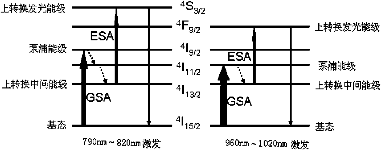
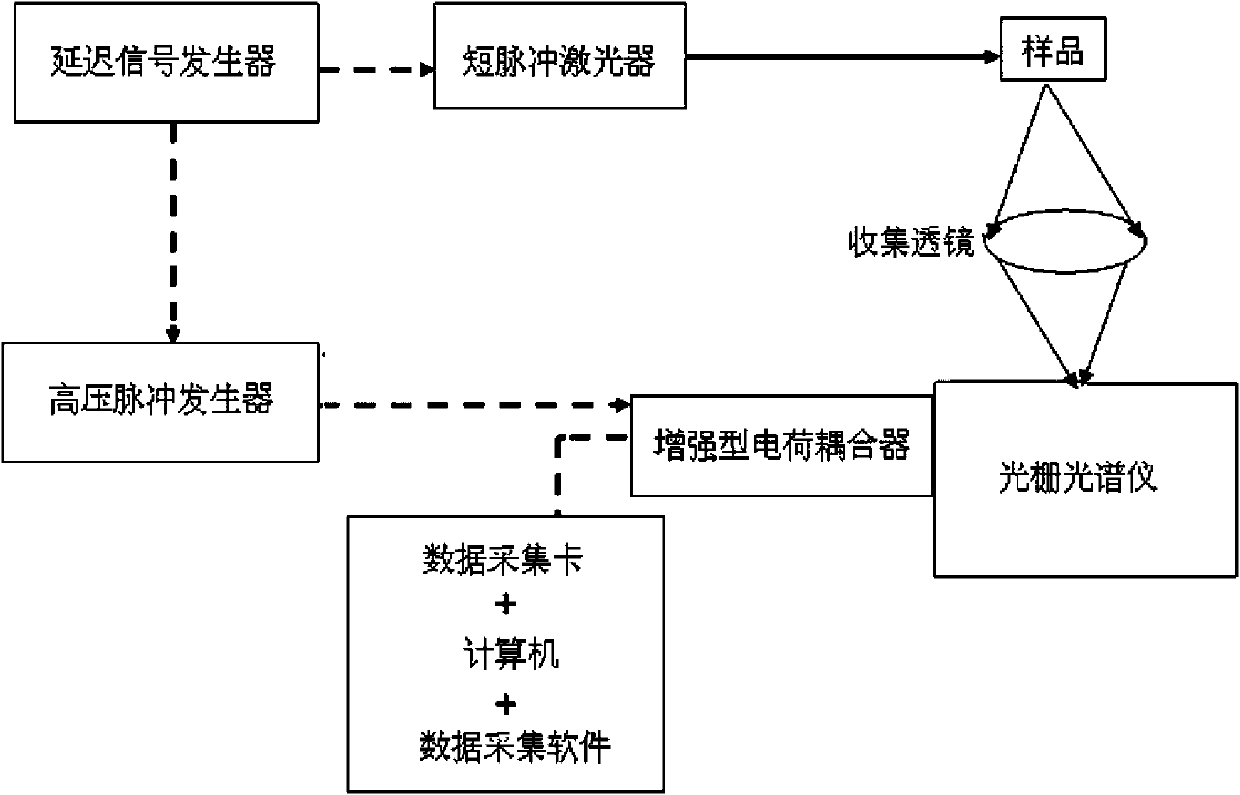
[0010] Specific implementation mode one: (see attached figure 2 ) The measuring method of a kind of erbium ion up-conversion intermediate energy level life-span of the present embodiment is carried out by the following steps: one, an output channel of delay signal generator is connected with the output control end of short pulse laser with coaxial cable, then connect The other output channel is connected with the external trigger port of the high-voltage pulse generator; then one output port of the high-voltage pulse generator is connected with the external trigger port of the enhanced charge coupler with a coaxial cable; the control port of the enhanced charge coupler is connected with the The data acquisition card is connected, and the data acquisition card is inserted on the motherboard of the computer; the enhanced charge coupler is inserted into the exit port of the grating spectrometer, and the pulse wavelength output by the short pulse laser is 790nm~820nm or 960nm~1020...

specific Embodiment approach 2

[0014] Embodiment 2: This embodiment differs from Embodiment 1 in that the pulse wavelength output by the short-pulse laser in Step 1 is 795 nm to 815 nm. Others are the same as in the first embodiment.

specific Embodiment approach 3

[0015] Embodiment 3: The difference between this embodiment and Embodiment 1 or 2 is that the pulse wavelength output by the short-pulse laser in Step 1 is 800 nm. Others are the same as in the first or second embodiment.


PUM


Abstract

The invention discloses a measuring method of up-conversion intermediate energy level lifetime of erbium ions and relates to the measuring method of fluorescence lifetime, and the measuring method can solve the problems that the existing measuring method of the infrared fluorescence lifetime needs an expensive infrared detector, the testing process is complicated, double beams and the delay change between the double beams need to be introduced, and the testing difficulty is great. The method adopts a delay signal generator, a short pulse laser, a high voltage pulse generator, an enhanced charge-coupled device and a grating spectrometer for constituting a testing system, and fluorescence emitted by a tested material by pulse radiation enters into the spectrometer for testing the light intensity; and the corresponding visible light intensities under different excitation frequencies are measured under the condition of keeping the single pulse energy unchanged, an I-1 / f relation map is drawn out, then fitting is carried out by utilizing the formula, and the fitted tau is the up-conversion intermediate energy level lifetime. The single beam is adopted and the visible light detector is used for measuring the infrared energy level fluorescence lifetime, the measuring process is simple, and the measuring method can be used for measuring the fluorescence lifetime of Er3+ doped materials.

Description

technical field [0001] The invention relates to a method for measuring fluorescence lifetime. Background technique [0002] Optical communication amplifiers are generally composed of Er 3+ prepared by ion-doped materials, Er 3+ The fluorescence lifetime of ions is an important reference data when designing optical communication amplifiers, so the accurate measurement of Er in materials 3+ The fluorescence lifetime of ions is very important, currently measuring Er 3+ The methods of ion fluorescence lifetime mainly include fast ion beam laser technology, delay coincidence single photon counting technology, pulse sampling technology, fluorescence up-conversion technology and pump detection technology, among which fast ion beam laser technology, delay coincidence single photon counting technology and pulse sampling The technology requires the monitoring of the fluorescence originating from the energy level to be measured. If the fluorescence of the energy level to be measured...

Claims


Application Information

Patent Timeline
Patent Type & Authority Patents(China)
IPC IPC(8): G01N21/64
Inventor 李艾华郑植仁刘伟龙
Owner HARBIN INST OF TECH
Learn More