
Ball screw pair experimental bench

A ball screw pair and ball screw technology, which is applied in the field of ball screw pair test benches, can solve problems such as the inability to accurately simulate the working conditions of high-speed and large-load ball screw pairs, difficulty in understanding product performance, and lack of detection methods. , to achieve the effects of wide load adjustable range, fast action speed and fast system response

Inactive Publication Date: 2012-05-30
ZHEJIANG UNIV
View PDF0 Cites 0 Cited by
  • Summary
  • Abstract
  • Description
  • Claims
  • Application Information

AI Technical Summary

Problems solved by technology

Without advanced testing methods, it is difficult to understand the performance of the product, and it is impossible to provide effective and comparable data for product improvement
At present, although the domestic ball screw pair performance tests are relatively comprehensive, they are all carried out when the load condition is no load or light load. The application range of the ball screw pair tested is mainly for transmission rather than load transmission, which cannot be accurately simulated. Working conditions of high speed and heavy load ball screw pair

Method used


Image

  • Ball screw pair experimental bench
  • Ball screw pair experimental bench

Examples


Embodiment Construction

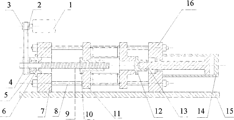
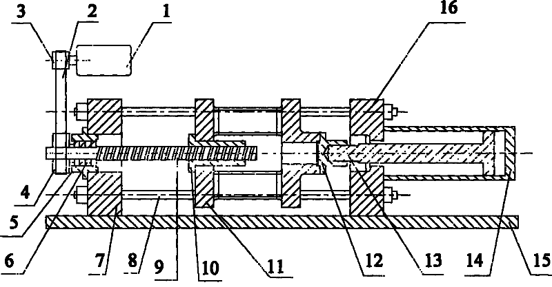
[0009] refer to figure 1 , the ball screw auxiliary test bench of the present invention includes a frame 15, a head plate 16 and a tail plate 7 are fixed on the frame 15, a connecting pull rod 8 is arranged between the head plate 16 and the tail plate 7, and a columnar Skateboard 11, one end of the columnar slideboard 11 is connected to the slideboard cover 12, the center hole of the other end of the columnar slideboard 11 is fastened with a ball nut 10, the ball screw 9 is supported on the tail plate 7 through the rolling bearing 6 and the bearing sleeve 5, the ball screw 9 One end of the ball screw 9 is screwed to the ball nut 10, the other end of the ball screw 9 is fixed with a large pulley 4, the large pulley 4 is connected with the small pulley 3 installed on the servo motor 1 through the toothed synchronous belt 2, and the head plate 16 One side of the hydraulic cylinder is fixed with a hydraulic cylinder 14, the piston rod 13 of the hydraulic cylinder passes through th...


PUM


Abstract

The invention discloses a ball screw pair experimental bench, comprising a stand. A head plate and a tail plate are fixed on the stand, a connecting tie bar is arranged between the head plate and the tail plate, the tie bar is provided with a cylindrical sliding plate, one end of the cylindrical sliding plate is connected with a sliding plate cover, a ball nut is fastened in a central hole of theother end of the cylindrical sliding plate, a ball screw is supported on the tail plate by a rolling bearing and a bearing housing, the ball nut is screwed at one end of the ball screw, a large belt wheel is fixed at the other end of the ball screw and is connected with a small belt wheel arranged on a servo motor by a synchronous tooth belt, a hydraulic cylinder is fixed at one side of the head plate, and a piston rod coaxial with the ball screw is connected with the sliding plate cover through the head plate. When the ball screw is driven by the servo motor to rotate and drives the ball nutto axially move forwards or backwards, the sliding plate and the piston rod move along with the ball nut, and the load of the ball screw can be regulated by regulating the pressure of a hydraulic oilcylinder. The experimental bench has stable performance, high operation speed, wide adjustable range of the load, high speed of system response and high precision.

Description

technical field [0001] The invention relates to a test bench for a ball screw pair. Background technique [0002] At present, high-speed and large-load ball screw pairs mainly rely on imports. Compared with advanced countries, there is still a certain gap between the development level of domestic high-speed and large-load ball screw pairs. In addition to factors such as the accuracy of raw materials and processing equipment, there is no perfect test and detection. Means are also an important reason restricting its development. Without advanced detection methods, it is difficult to understand the performance of the product, and it is impossible to provide effective and comparable data for product improvement. At present, although the domestic ball screw pair performance tests are relatively comprehensive, they are all carried out when the load condition is no load or light load. The application range of the ball screw pair tested is mainly for transmission rather than load t...

Claims


Application Information

Patent Timeline
Patent Type & Authority Patents(China)
IPC IPC(8): G01M13/02
Inventor 李凌丰罗容
Owner ZHEJIANG UNIV
Learn More