Velocity detection method and motor control device using the method

A technology of speed detection and speed, which is applied in measuring devices, linear/angular speed measurement, speed/acceleration/shock measurement, etc., and can solve the problem of large fluctuations in detection speed

Inactive Publication Date: 2010-07-21
YASKAWA DENKI KK
View PDF1 Cites 6 Cited by
  • Summary
  • Abstract
  • Description
  • Claims
  • Application Information

AI Technical Summary

Problems solved by technology

In addition, when using a pulse generating circuit equipped with a tracking circuit, if the speed calculation sampling period is not an integral multiple of ...

Method used


Image

  • Velocity detection method and motor control device using the method
  • Velocity detection method and motor control device using the method
  • Velocity detection method and motor control device using the method

Examples


Embodiment

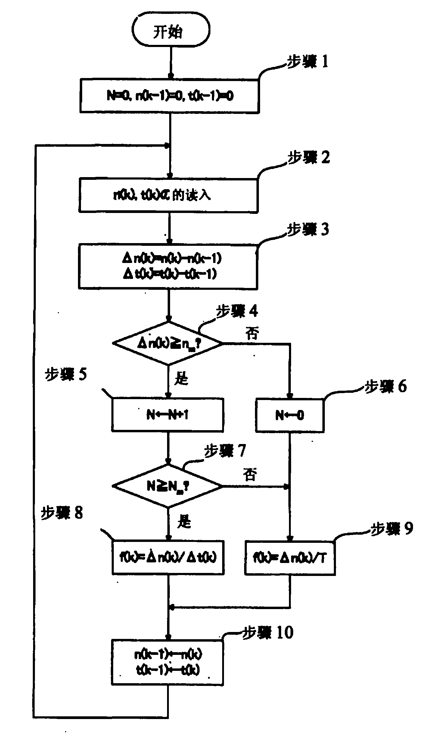
[0044] The composition and the speed detection device of implementing the method of the present invention figure 2 The prior art shown is the same. figure 1 yes means figure 2 A flowchart of the processing sequence of the speed detection method of the present invention of the speed detection device. Next, use figure 1 The method of the present invention will be described in order.

[0045] First, in order to perform the initialization process in step 1, the number of consecutive multi-pulse consecutive times N, the previous position pulse value n(k-1), and All the previous timer values ​​t(k-1) become 0.

[0046] Next, in step 2, send the read-out signal 10 by the speed arithmetic unit 6 and read in this position pulse value n(k) from the position register 3, and read in this timer value t(k) from the time register 5 .

[0047] In step 3, the change pulse value Δn(k) and the change timer value Δt(k) are obtained as shown in equations (1) and (2) as in the prior art.

...


PUM


Abstract

It is possible to provide a velocity detection method which can detect a highly-accurate and low-ripple velocity in a high-velocity region and can calculate a velocity without degrading the control performance even when a plenty of noises are contained in a low-velocity region. The velocity detection method uses a velocity detection device including: a pulse generation circuit (1) which outputs a position pulse; a counter (2) for counting the number of position pulses; a position register (3) which latches the value of the counter (2); a timer (4); a timer register (5) which stores the timer value by the up-down of the position pulse; and a velocity calculator (6) which issues a read-enable signal and reads the position pulse value from the position register (3) and the timer value from the timer register (5) so as to calculate a velocity. When the change pulse has reached a change pulse threshold value and the number of occurrences of the multi pulses has reached a multi-pulse continuous occurrence threshold value, the change pulse is divided by the change timer. Otherwise, the change pulse is divided by a sampling cycle to perform a velocity calculation process.

Description

technical field [0001] The present invention relates to a method for detecting the speed of a motor from the output of an encoder attached to the motor when performing feedback control of a servo motor. Background technique [0002] Usually, the speed detection of rotating bodies such as motors uses the counter value of the position pulse signal to be read at each specified sampling period, and the count difference between the read current counter value and the previous counter value is obtained, and divided by the count difference A pulse counting method to obtain the speed in the sampling cycle. If you want to improve the speed resolution, you need a high-resolution pulse generation circuit. In addition, when using a pulse generating circuit equipped with a tracking circuit, if the velocity calculation sampling period is not an integral multiple of the tracking sampling period, there is also a problem that a beat phenomenon occurs and fluctuations in the detection velocit...

Claims


Application Information

Patent Timeline
IPC IPC(8): G01P3/489H02K29/14H02P6/16
CPCG01P3/489
Inventor 竹井康行张文农中村裕司
Owner YASKAWA DENKI KK
Why Eureka
Try Eureka