Eureka AIR delivers breakthrough ideas for toughest innovation challenges, trusted by R&D personnel around the world.

Earphone interface circuit and electronic equipment

An earphone interface and earphone technology, applied in the electronic field, can solve the problem of inability to accurately detect whether the earphone is in the plugged state and the like

Inactive Publication Date: 2010-07-21
QINGDAO HISENSE MOBILE COMM TECH CO LTD
View PDF4 Cites 35 Cited by
  • Summary
  • Abstract
  • Description
  • Claims
  • Application Information

AI Technical Summary

Problems solved by technology

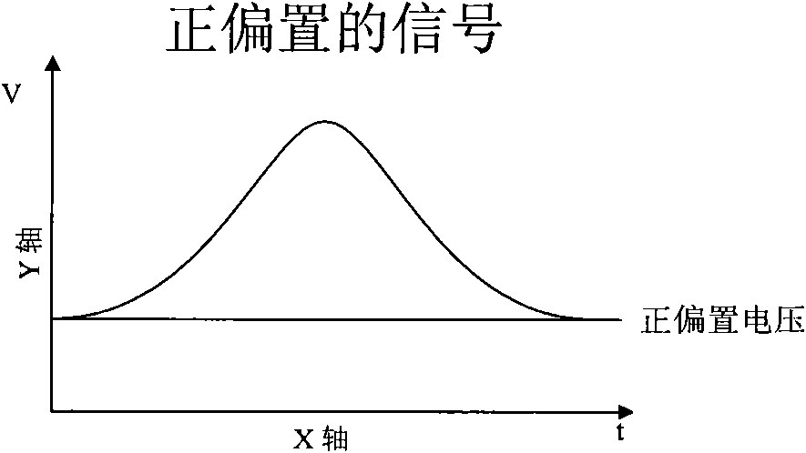
[0019] The embodiment of the present invention provides an earphone interface circuit and an electronic device equipped with the earphone interface circuit, which solves the problem that the existing earphone interface circuit cannot accurately detect whether the earphone is in the inserted state when the audio signal is a signal without bias voltage technical issues

Method used


Image

  • Earphone interface circuit and electronic equipment
  • Earphone interface circuit and electronic equipment
  • Earphone interface circuit and electronic equipment

Examples


Embodiment 1

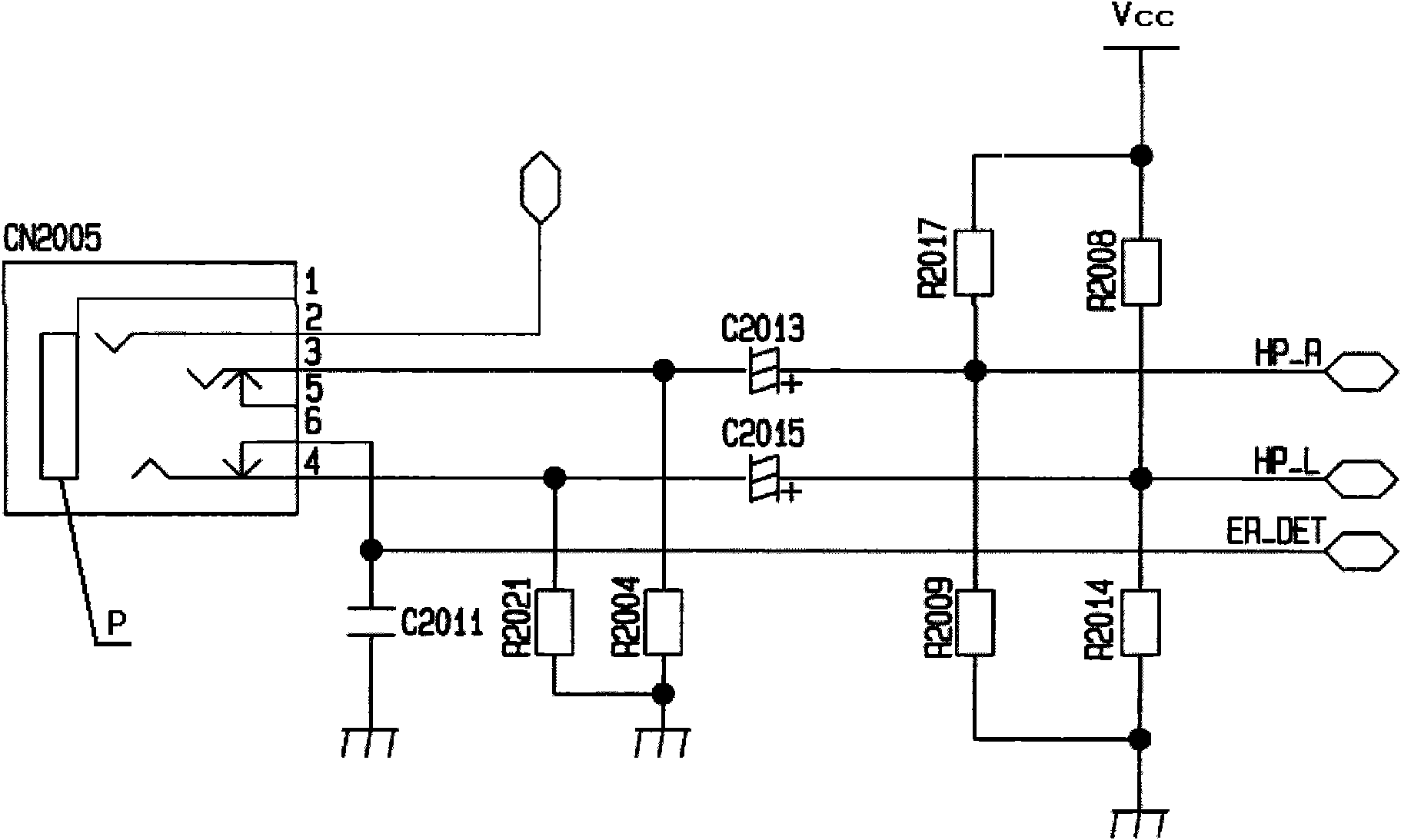
[0059] Such as Image 6 with Figure 7 As shown, the earphone interface circuit provided by the embodiment of the present invention includes socket port P, audio signal output pins OR, OL, audio input pin 2, ground pin 8, elastic pin 7, earphone state test terminal DET2, The power supply module 10 and the control detection module 11, wherein:

[0060] The socket port P is connected to the ground pin 8, and when the earphone is inserted into the socket port P and is in the inserted state, the grounding part of the earphone abuts against the socket port P;

[0061] The earphone in the inserted state receives the left channel audio signal and / or the right channel audio signal through the audio signal output pins OR and OL;

[0062] One end of the audio input pin 2 is abutted against and electrically connected to the elastic pin 7, and the other end is connected to the control detection module 11, and the elastic pin 7 is connected to the control detection module 11 through the ...

Embodiment 2

[0086] Please also refer to Figure 8 , this embodiment is basically the same as Embodiment 1, the difference is that: in this embodiment, the power supply module 10 includes a third power supply terminal V3 and a fourth field effect transistor Q4, wherein:

[0087] The source of the fourth field effect transistor Q4 is connected to the third power supply terminal V3, and its drain is connected in parallel with the earphone type identification terminal DET1 through the sixth resistor R6 and then connected to the audio input pin 2. There is also a gap between the source and the drain. A seventh resistor R7 is connected, and an eighth resistor R8 is connected between the earphone type identification terminal DET1 and the audio input pin 2 .

[0088] When the three-segment earphone is inserted into the socket port P and is in the inserted state, the grounding part c of the three-segment earphone is in contact with the audio input pin 2, and at this time, the audio input pin 2 is ...


PUM


Abstract

The invention discloses an earphone interface circuit and electronic equipment, relating to the technical field of electrons and solving the technical problem that the traditional earphone interface circuit can not accurately detect whether an earphone is in an inserting state or not when an audio signal is a non-biased voltage signal. The earphone interface circuit comprises a socket interface, an audio signal output pin, an audio input pin, a grounding pin, an elastic pin, an earphone state testing end, a power supply module and a control detection module, wherein the socket interface is connected with the grounding pin; when the earphone is inserted into the socket interface and in the inserting state, the grounding part of the earphone abuts against the socket interface; the power supply module is connected with the audio input pin and used for inputting electric energy to the audio input pin; and the control detection module is connected with the earphone state testing end and used for judging whether the earphone is in the inserting state or not according to the change of a level at the earphone state testing end. The electronic equipment comprises the earphone interface circuit. The invention is applied to the electronic equipment provided with the earphone interface circuit.

Description

technical field [0001] The invention relates to the field of electronic technology, in particular to an earphone interface circuit and electronic equipment provided with the earphone interface circuit. Background technique [0002] With the continuous development of electronic technology, earphones have become one of the indispensable important devices on electronic equipment such as mobile phones and computers. [0003] When the earphone is plugged into the earphone jack and is in the plugged state, it can be connected to the control and detection module of the electronic device through the earphone interface circuit. The control and detection module of the electronic device inputs an audio signal to the earphone through the earphone interface circuit, and the speaker of the earphone recognizes the audio signal And play out the sound corresponding to the audio signal, the microphone of the earphone can receive the user's voice, convert the user's voice into an audio signal,...

Claims


Application Information

Patent Timeline
IPC IPC(8): H04R1/10
Inventor 张秀梅臧美慧杜英潘蓓王瑞娟汪翠兰罗运霞于海泳熊庆华
Owner QINGDAO HISENSE MOBILE COMM TECH CO LTD
Why Eureka
Eureka Blog
Learn More