
Side reverse-type reflector

A technology of reflectors and reflector arrays, applied in reflectors, semiconductor devices of light-emitting elements, outdoor lighting, etc., can solve the problems of reducing light sources, high cost, and easy aging of lenses, and achieve uniform intensity distribution, long life and high efficiency effect

Inactive Publication Date: 2010-07-21
OSRAM GMBH
View PDF3 Cites 6 Cited by
  • Summary
  • Abstract
  • Description
  • Claims
  • Application Information

AI Technical Summary

Problems solved by technology

However, due to the use of optical lenses, which are usually made of resin, in the case of high-power light sources, the lenses are prone to aging, thereby shortening the service life of the lamps
If a lens made of glass is used, on the one hand, the cost of the manufacturing process is relatively high, and on the other hand, the lamp is also relatively vulnerable to damage
If the power of the light source is reduced in order to ensure the service life of the lamp, the brightness required by the application cannot be achieved

Method used


Image

  • Side reverse-type reflector
  • Side reverse-type reflector
  • Side reverse-type reflector

Examples


Embodiment Construction

[0020] Exemplary embodiments of the present invention will be described below with reference to the accompanying drawings. In the interest of clarity and conciseness, not all features of an actual implementation are described in this specification. However, it should be understood that many implementation-specific decisions must be made in developing any such practical implementation in order to achieve the developer's specific goals, and that these decisions may vary from implementation to implementation . Furthermore, it should also be understood that development work, while potentially complex and time-consuming, would at least be a routine undertaking for those skilled in the art having the benefit of this disclosure.

[0021] Here, it should also be noted that, in order to avoid obscuring the present invention due to unnecessary details, only the device structure closely related to the solution according to the present invention is shown in the drawings, and the relation...


PUM


Abstract

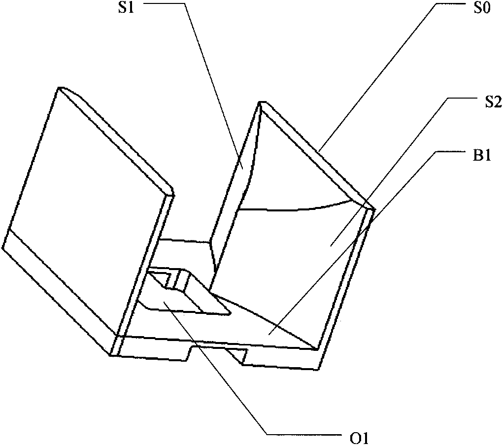
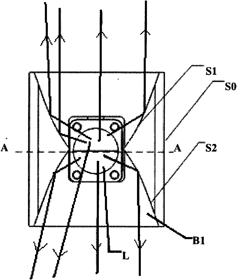
The invention discloses a side reverse-type reflector. The side reverse-type reflector comprises a bottom opening so that a light source arranged on a substrate can be contained in the bottom opening; and reflecting surfaces are arranged at two opposite sides of the light source on the side reverse-type reflector and are configured to laterally reflect the light which is sent by the light source and is emitted into the reflecting surface so that the emitted light deflects towards the direction parallel to the opposite sides. The invention also provides an array of the side reverse-type reflector. Furthermore, the invention also discloses a luminaire unit with the side reverse-type reflector, a lamp and a method for manufacturing the side reverse-type reflector.

Description

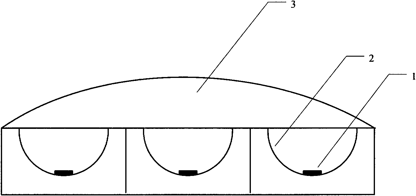
technical field [0001] The invention relates to a side reflector, in particular to a side reflector applied to general lighting, and especially to a side reflector applied to street lamps. Background technique [0002] In a common luminaire, in order to shape the light emitted from the light source, the light source (such as a light emitting diode LED) is usually arranged in a reflector cup and / or shaped by means of a lens. For example, attach figure 1 A solution in the prior art is shown. Wherein, the light source 1 is arranged in the groove 2 . The surface of the groove 2 is coated with a reflective material as a mirror, so that the light output by the light source 1 is close to parallel light. An optical lens 3 is arranged above the groove 2, and the angle of the output light can meet application requirements by using the optical lens 3. However, due to the use of optical lenses, and the lenses are usually made of resin, in the case of high-power light sources, the le...

Claims


Application Information

Patent Timeline
IPC IPC(8): F21V7/04F21V7/10F21Y101/02F21W131/103
CPCF21V7/22F21V7/05F21S8/08F21V7/00F21Y2101/02F21W2131/103F21V7/04F21Y2115/10F21V7/24
Inventor 何锡源马克斯·尤埃罗亚斌
Owner OSRAM GMBH
Learn More