Printer

A technology for printing machines and cranes, which is applied in the direction of printing machines, printing, rotary printing machines, etc. It can solve the problems of machine damage, temperature treatment liquid ingress, and lubricating ability reduction, and achieve the effect of reducing work

Inactive Publication Date: 2013-08-07
HEIDELBERGER DRUCKMASCHINEN AG
View PDF2 Cites 1 Cited by
  • Summary
  • Abstract
  • Description
  • Claims
  • Application Information

AI Technical Summary

Problems solved by technology

There is a risk that, in the event of a leak caused by a fault, temperature-processing liquid (water) enters the lubricant circuit and the oil is contaminated
Due to this contamination, the lubricating ability of said oil will be reduced, which will lead to machine damage

Method used


Image

  • Printer
  • Printer
  • Printer

Examples


Embodiment Construction

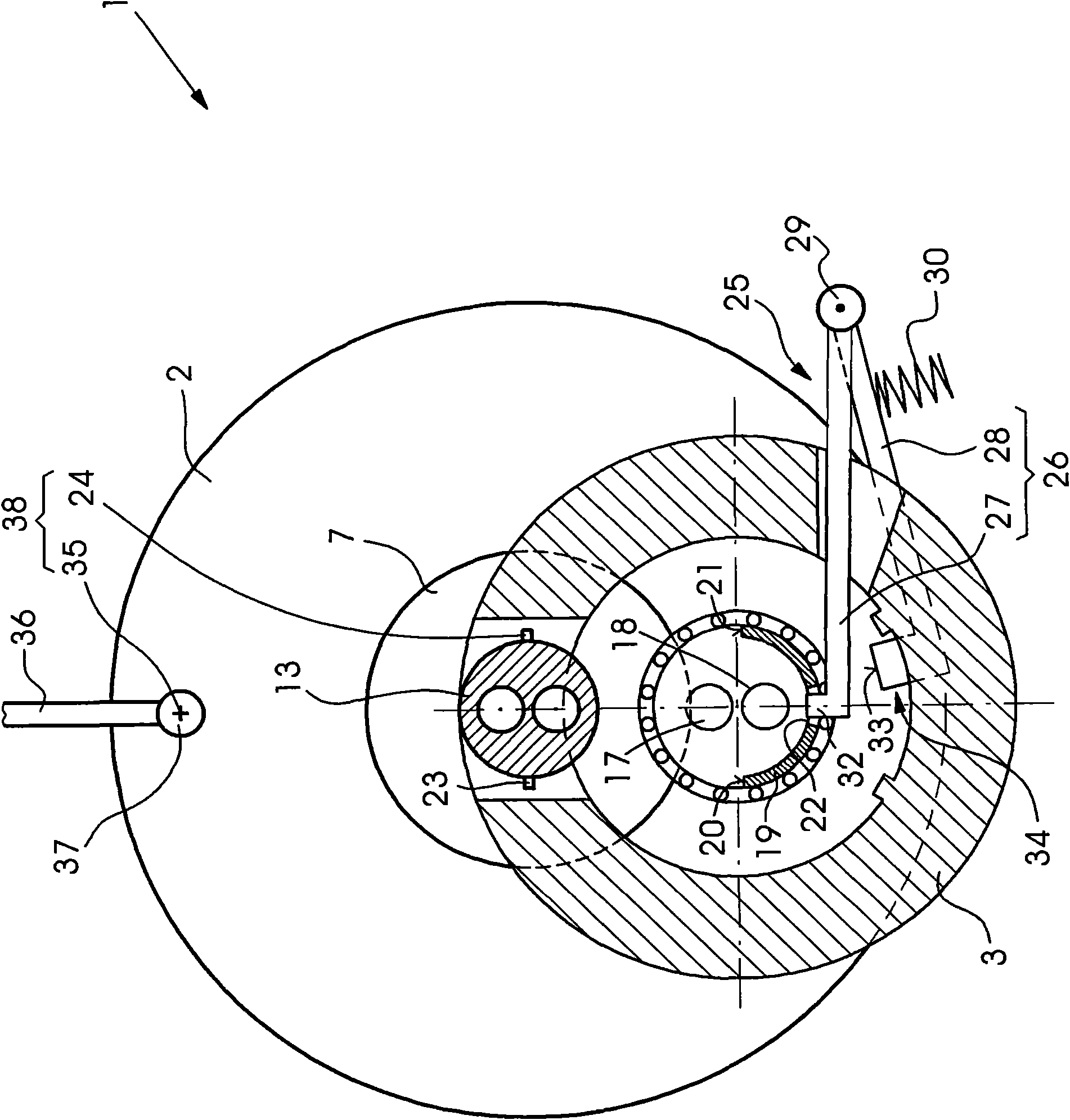
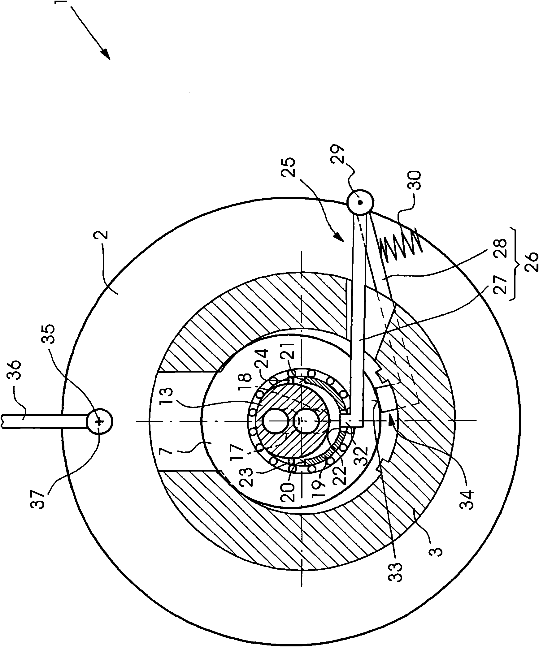
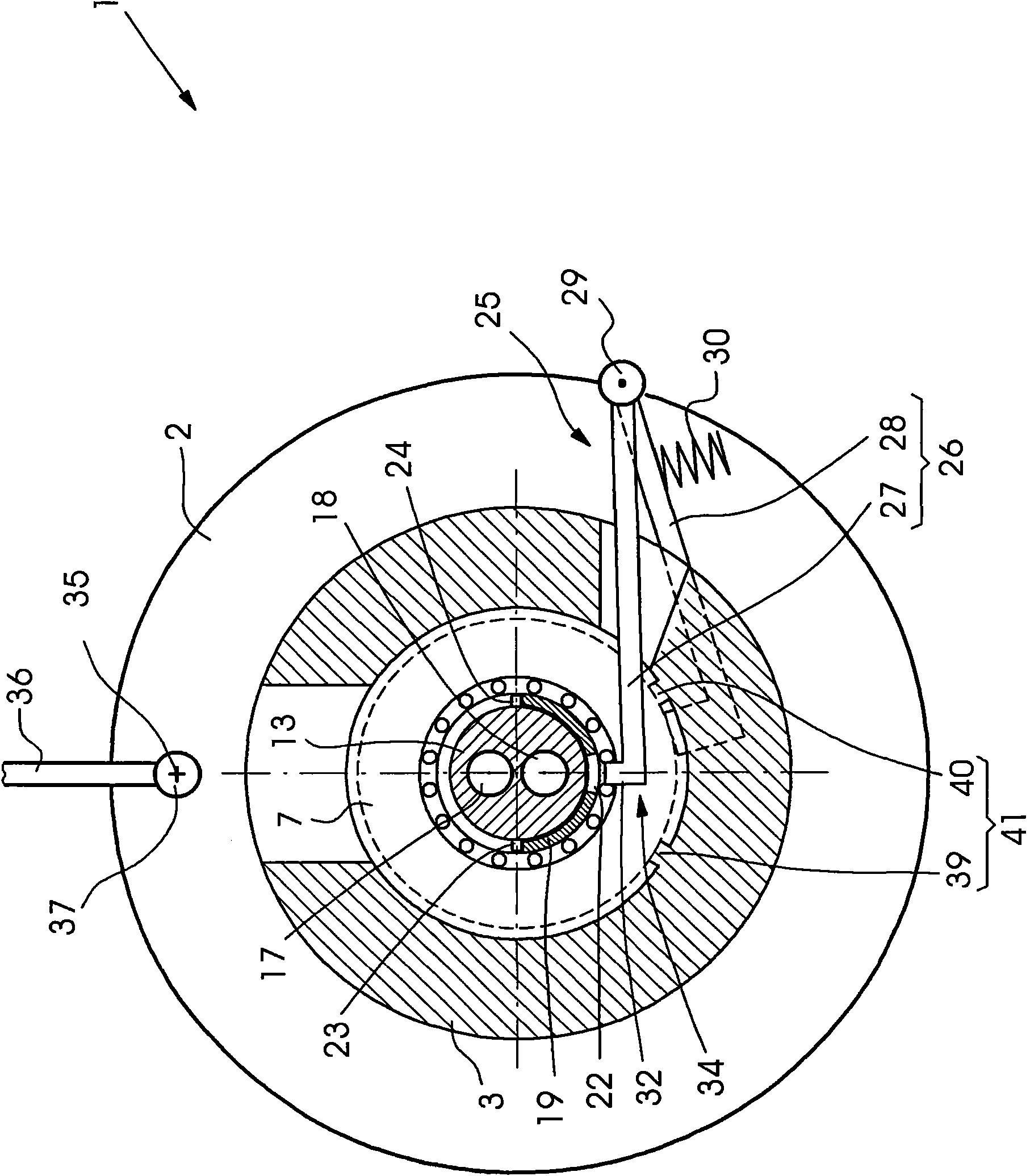
[0019] exist Figures 1 to 4 As shown in , the printing press 1 comprises a roller 2 and roller locks 3, 4 arranged to receive the roller. The printing press 1 is an offset printing press and the roller 2 is an anilox roller of an anilox inking unit. One roller lock 3 is on the operating side BS of the printing press 1 and the other roller lock 4 is on the driving side AS.

[0020] The roll 2 has journals 5, 6 on which rolling bearings 7, 8 sit. On the drive side AS, a drive shaft 9 is mounted rotatably via roller bearings in the wall of the machine frame and in the roller lock 4 . A gear 10 is connected to the drive shaft 9 in a rotationally fixed manner, which is a component of a gear transmission.

[0021] The first clutch half of a drive clutch 11 is situated on the journal 6 , the second clutch half of which is situated on the end of the drive shaft 9 opposite the gear wheel 10 . The drive clutch 11 serves to transmit torque from the drive shaft 9 to the roller 2 and ...


PUM


Abstract

The machine (1) has a roller (2) via which a tempering fluid i.e. water, flows. Roller locks (3) lock the roller and are designed as fast replacement devices. An electric coupler connects a tempering fluid pipeline with the roller. The electric coupler has a coupling half (13) provided at the roller, and another coupling half provided at the pipeline. A positioning device (38) adjusts or aligns a correct angle position of one of the coupling half relative to the other half in an automatic manner during insertion of roller into the locks.

Description

technical field [0001] The invention relates to a printing machine comprising a roller through which a temperature-treatment liquid flows, a roller lock for the roller which is designed as a quick-change device, and a line for the temperature-treatment liquid to be connected to the A roller-attached line clutch, wherein the line clutch has a first clutch half on the roller and a second clutch half on the line. Background technique [0002] Such a printing press is described in DE 10 2005 049 176 A1. In this case, the rollers are supported in roller locks designed as quick-change devices or quick-release locking devices, so that the rollers can be quickly removed from the roller locks and the printing press by an operator of the printing press and inserted again into the roller locks and the printing press. in the printing press. With regard to the maintenance of the rollers outside the printing press, the configuration of the roller lock as a quick-change device and the re...

Claims


Application Information

Patent Timeline
Patent Type & Authority Patents(China)
IPC IPC(8): B41F31/00B41F31/30
CPCB41F13/20B41F13/22
Inventor C·卡岑贝格尔R·米勒D·沙夫拉特B·施瓦布
Owner HEIDELBERGER DRUCKMASCHINEN AG
Why Eureka
Try Eureka