Double-layer injection mold

A double-layer injection molding and mold technology, which is applied in the field of plastic molds, can solve the problems of inability to install small injection machines, increase the length and width of molds, and increase injection molding costs, so as to avoid increased injection molding costs, improve production efficiency, and occupy less space. Effect

Inactive Publication Date: 2010-07-21
ZHEJIANG KAIHUA MOLDS
View PDF0 Cites 4 Cited by
  • Summary
  • Abstract
  • Description
  • Claims
  • Application Information

AI Technical Summary

Problems solved by technology

The molding parts of the injection mold include a cavity and a core. The cavity and the core constitute the cavity of the product. In order to improve production efficiency, multiple cavities are generally arranged in the cavity and the core, so as to realize the molding of multiple products at one time. As is usually said, one out of three, one out of four, etc., but after the number of mold cavities increases, especially when the number of mold cavities is particularly large, such as one out of twelve, one out of sixteen, etc., the length of the mold will inevitably be greatly increased. The wide size will take up a lot of space, and when the length and width of the mold become larger, it cannot be installed on a small injection machine, and if a large injection machine is used, the injection molding cost will be greatly increased

Method used


Image

  • Double-layer injection mold
  • Double-layer injection mold
  • Double-layer injection mold

Examples


Embodiment Construction

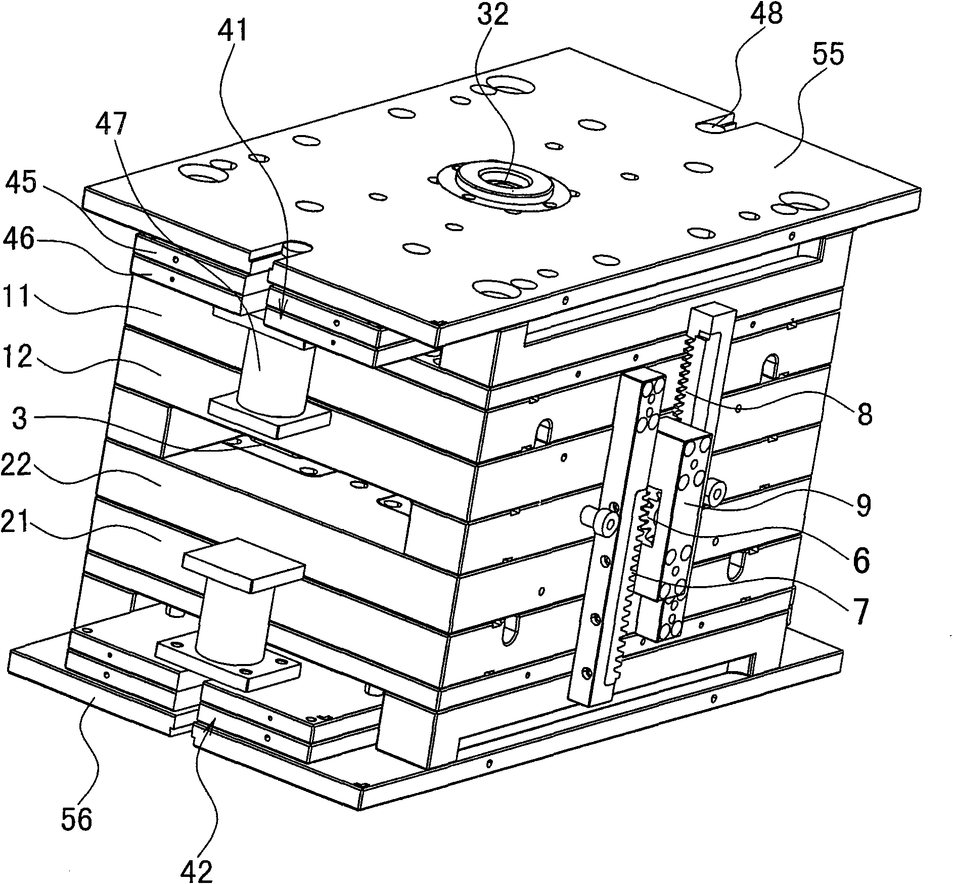
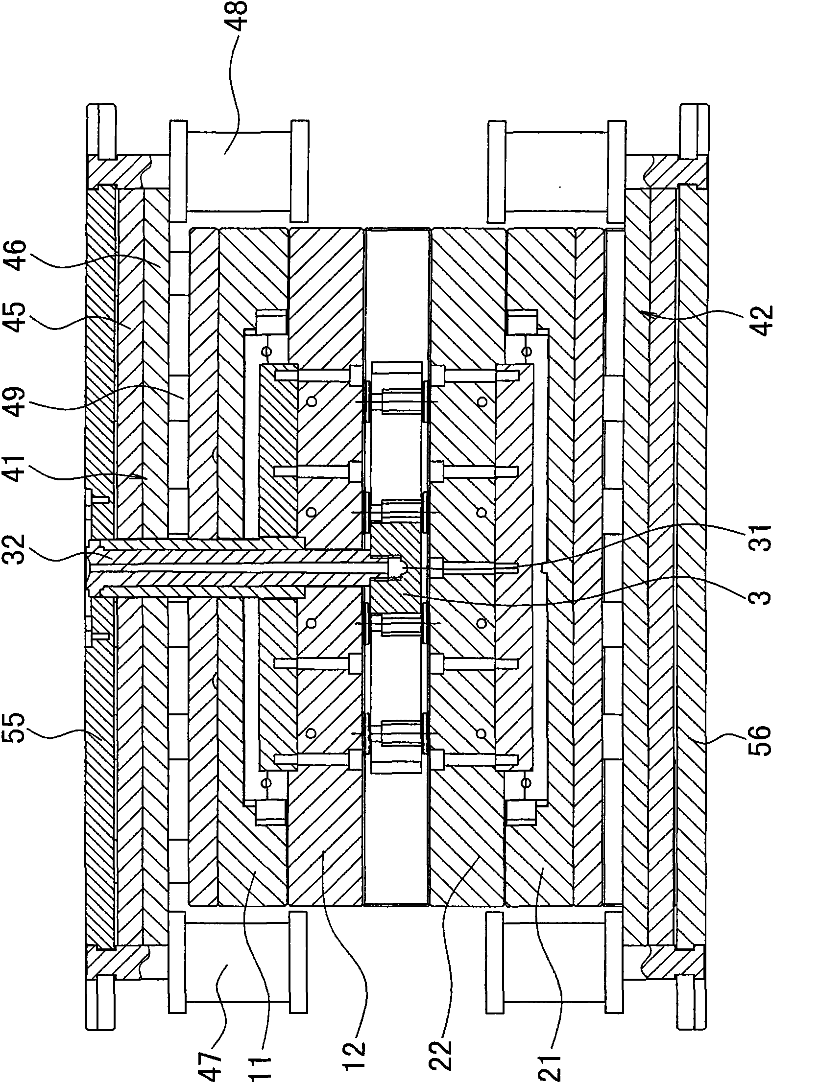
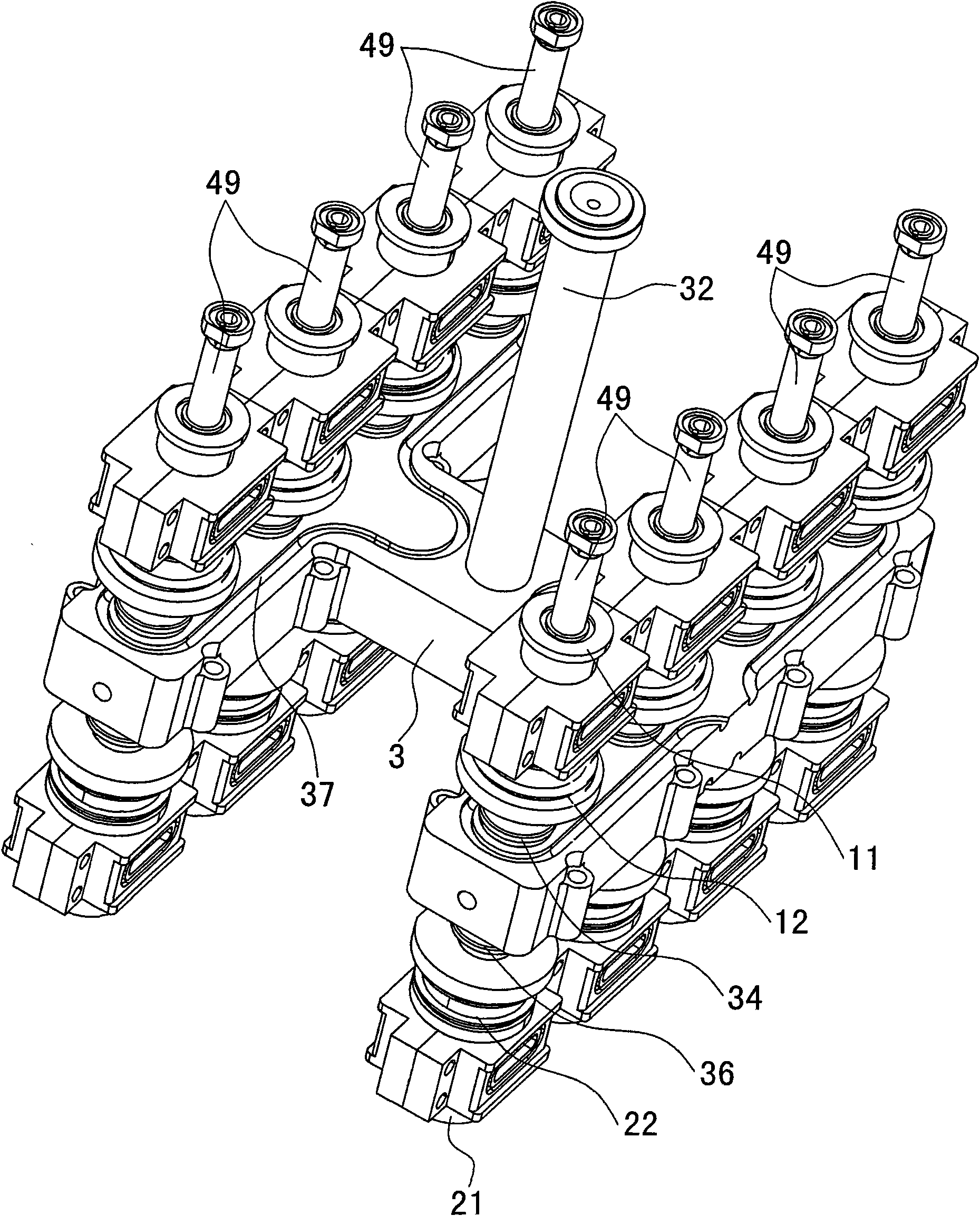
[0012] The present invention relates to a double-layer injection mold, such as Figure 1-Figure 5 As shown, including the core and the cavity, the core and the cavity constitute the cavity of the product, the cavity is two or more, the core and the cavity can be integrally manufactured, but because the cavity and the core The required materials are better. In order to save precious metal materials and reduce costs, the cavity and core are generally manufactured separately, such as image 3 , Figure 4 As shown, the cavity and the core used for the molding part are made into inserts respectively, and then the inserts are inserted into the cavity fixing plate and the core fixing plate, and the cavity fixing plate and the core fixing plate can be used For ordinary materials, when there are many cavities, there are multiple cavity inserts and core inserts, each forming a cavity. The products in the cavity are driven by the ejector mechanism, and the outer wall of the cavity is pr...


PUM


Abstract

The invention discloses a double-layer injection module, which comprises mold cores and mold cavities, wherein the mold cores and the mold cavities form two or more than two product molding chambers; the mold cores are driven by an ejecting mechanism; the outer walls of the mold cavities are provided with pouring openings; and one end of each pouring opening is communicated with one molding chamber and the other ends of the pouring openings are communicated with a hot runner plate connected with a spray nozzle of an injection machine. The double-layer injection module is characterized in that: the mold cores and the mold cavities are both comprised of upper and lower layers; the upper-layer mold core and the upper-layer mold cavity are positioned above the hot runner plate; the lower-layer mold core and the lower-layer mold cavity are positioned below the hot runner plate; products in an upper-layer molding chamber and a lower-layer molding chamber are driven by the ejecting mechanism respectively; a branch runner is formed in the middle part of the hot runner plate; the branch runner is communicated with the spray nozzle of the injection machine through a main spray nozzle; the upper and lower wall faces of the branch runner are provided with plastic flow holes respectively; the upper plastic flow holes are communicated with the pouring opening of the upper-layer mold cavity through a first hot spray nozzle respectively; the lower plastic flow holes are communicated with the pouring openings on the lower-layer mold cavity through a second hot spray nozzle; and auxiliary mold opening mechanisms are arranged on the left and right two sides of the hot runner plate respectively.

Description

technical field [0001] The invention relates to a plastic mold, in particular to a double-layer injection mold, and belongs to the field of plastic molds. Background technique [0002] Due to the fast molding of plastic products, it has developed rapidly. There are many molding methods of plastic products, such as injection molding, extrusion molding, blow molding and so on. The molding parts of the injection mold include a cavity and a core. The cavity and the core constitute the cavity of the product. In order to improve production efficiency, multiple cavities are generally arranged in the cavity and the core, so as to realize the molding of multiple products at one time. As is usually said, one out of three, one out of four, etc., but after the number of mold cavities increases, especially when the number of mold cavities is particularly large, such as one out of twelve, one out of sixteen, etc., the length of the mold will inevitably be greatly increased. The wide siz...

Claims


Application Information

Patent Timeline
Patent Type & Authority Applications(China)
IPC IPC(8): B29C45/26
Inventor 王春方李过梁正华
Owner ZHEJIANG KAIHUA MOLDS
Why Eureka
Try Eureka