Strip mop with mechanical wiping device
A technology of squeezing device and mop, which is applied in the field of mop, and can solve the problems of low mopping efficiency, insufficient cleaning, inconvenient use, etc.
- Summary
- Abstract
- Description
- Claims
- Application Information
AI Technical Summary
Problems solved by technology
Method used
Image


Examples
Embodiment 1
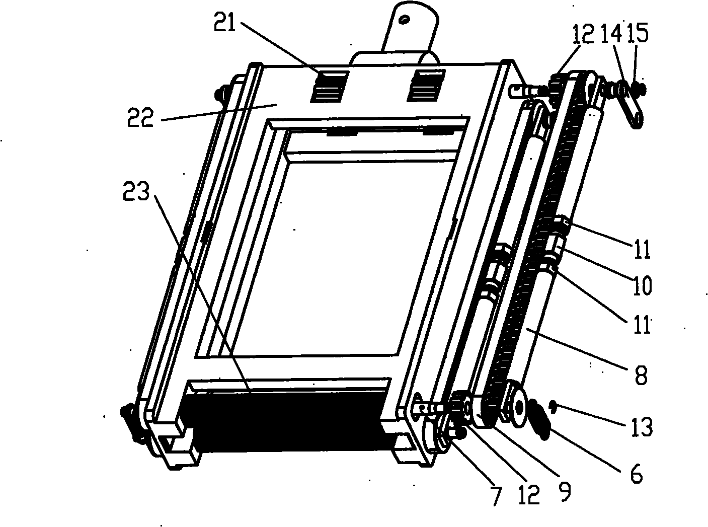
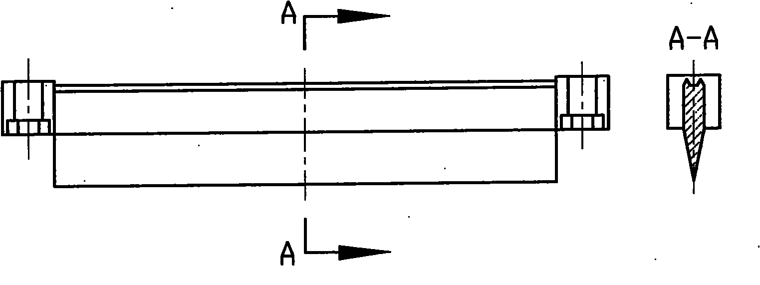
[0073] Embodiment 1, the synchronous belt transmission mechanism has adopted the roller type mop of 4 groups of synchronous belt transmission units, in figure 1 Place the square mop 1 between the lower mop head clip 3 and the upper mop head clip 4, and lock it with bolts 2 to form a mop head. exist figure 1 , image 3 , Image 6 There are square uprights 3-1 on both sides of the middle and lower drag head clamp 3, and a through hole 32 in the center of the uprights. The cross-sectional section A-A of the part holding the strip between the two uprights is a pentagon 3-3, and the pentagon can be decomposed into a rectangle. and the two parts of the isosceles triangle, and the rectangular side opposite to the base of the isosceles triangle is pasted on the cloth strip, that is, the part holding the strip is a pentagonal prism, and the surface of the side holding the cloth strip has ribs 3-4, and the ribs and the pentagonal prism The edges are parallel; in Figure 4 , Figure...
Embodiment 2
[0074] Embodiment two, adopt the pressure plate type mop of top block and one-way stop hook mechanism, in Figure 12 , Figure 14 Place the square mop 24 between the lower mop head clip 26 and the upper mop head clip 27 and clamp it with bolts 25 to form a mop head. exist Figure 17 There are rectangular columns 26-1 on both sides of the middle and lower drag head clip 26, and a through hole 26-2 in the center of the column. The cross-sectional section D-D of the strip part between the two columns is a pentagon 26-3, and the pentagon can be decomposed. It consists of two parts: a rectangle and an isosceles triangle. The side of the rectangle opposite to the base of the isosceles triangle is pasted on the cloth strip, that is, the part holding the strip is a pentagonal prism, and there is a jagged rib in the center of the surface of the side holding the cloth strip. Teeth 26-4, the ribs are parallel to the ribs of the pentagonal prism; at Figure 15 Among them, there are cub...
Embodiment 3
[0075] Embodiment 3, combining the top block and the slide block for use, canceling the compression springs on the slide block and the mop bar, changing the shape of the top block to a spindle shape with a big center and two small ends; Install two upper and lower pressure wheels on the top, the upper pressure wheel is used to drive the pressure rod to squeeze the mop, and the lower pressure wheel is used to drive the pressure rod to clamp the positioning guide column; use the pressure claw to replace the middle pressure plate in the second embodiment, and use the cylindrical shape correspondingly The mop head and the frame adopt a stop plate mechanism in the mop head positioning guide post, and three pressure claws are used, so that it becomes a long pressure bar three-claw mop as shown in Figure 51. Its structural features different from Embodiment 2 and its assembly and operation process are set forth below:
[0076] exist Figure 28 Among them, the circular mop head is ma...
PUM
 Abstract
Description
Claims
Application Information
 - R&D
- Intellectual Property
- Life Sciences
- Materials
- Tech Scout
- Unparalleled Data Quality
- Higher Quality Content
- 60% Fewer Hallucinations
Browse by: Latest US Patents, China's latest patents, Technical Efficacy Thesaurus, Application Domain, Technology Topic, Popular Technical Reports.
© 2025 PatSnap. All rights reserved.Legal|Privacy policy|Modern Slavery Act Transparency Statement|Sitemap|About US| Contact US: help@patsnap.com