Eureka AIR delivers breakthrough ideas for toughest innovation challenges, trusted by R&D personnel around the world.

Design method and device of corn sheller

A design method and threshing machine technology, applied in threshing equipment, agricultural machinery and implements, applications, etc., can solve the problems of belt connection power output, slow granule separation speed, low production efficiency, etc., and achieve large propulsion and continuous Good, easy to process effect

Inactive Publication Date: 2010-07-21
袁毅
View PDF1 Cites 4 Cited by
  • Summary
  • Abstract
  • Description
  • Claims
  • Application Information

AI Technical Summary

Problems solved by technology

[0002] Although the known patent 02145589.9 corn threshing machine has high threshing cleanliness, the production efficiency is low due to the slow separation speed of granulation, and the original patent is more suitable for threshing dry corn with or without husk and threshing wet corn without husk. The threshing separation rate and clarity rate of wet corn with skin are affected. The original model can only be connected to the power output of the belt, and the improved model can be connected to PTO and other power outputs. At the same time, the spikes and concave plates of the original model The sieve, the main roller and the sieve hole have been improved to further improve the production efficiency, and the front movable slide plate, the rear fixed slide plate and the three-point suspension seat have been added.

Method used


Image

  • Design method and device of corn sheller
  • Design method and device of corn sheller
  • Design method and device of corn sheller

Examples


Embodiment 1

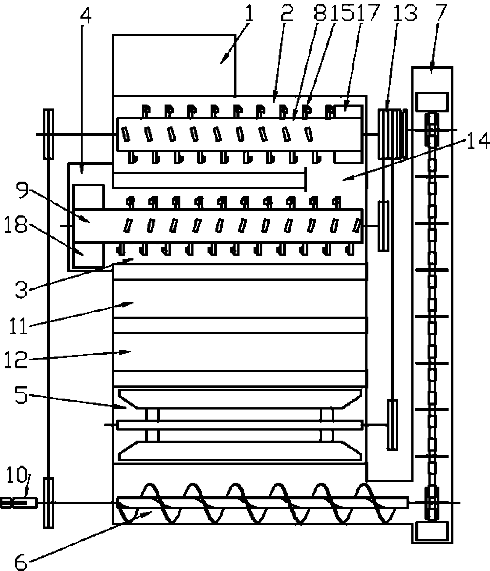
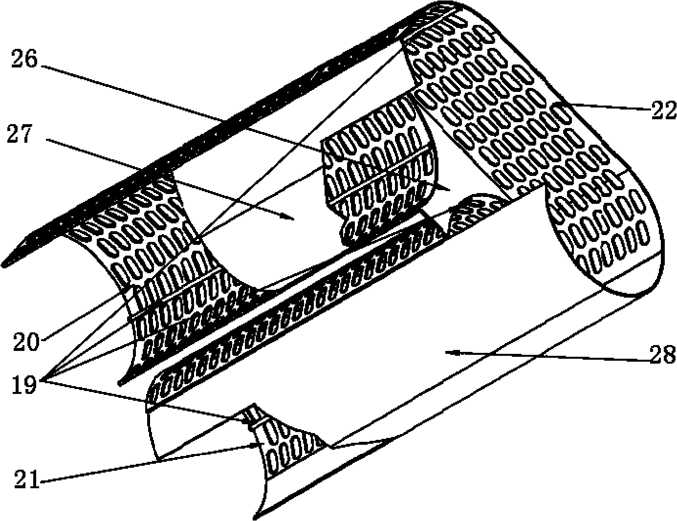
[0029] Embodiment 1: Its power transmission mechanism, threshing mechanism, conveying mechanism, impurity cleaning mechanism and frame five major structures and the connection relationship between these five parts are basically similar to known technology, or with patent No. 02145589.9 corn thresher The structure is basically the same, and the difference is that the roller of its threshing mechanism has sieve holes 16, and the longitudinal direction of the sieve holes 16 is longer than the horizontal direction, and the length and width ratio is 1.1:1 to 5:1. In this way, the throughput is increased while ensuring the quality of the pellets. Patent No. 02145589.9 corn thresher is easily blocked by corn husks and the like.

Embodiment 2

[0030] Embodiment 2: It is basically the same as Embodiment 1, except that its threshing mechanism has a plurality of protrusions 19 evenly distributed on the inner surface of the roller with screen holes 16 .

Embodiment 3

[0031] Embodiment 3: It is also basically the same as Embodiment 1, the difference is that the nail teeth 15 distributed on the main roller 8 and the auxiliary roller 9 are composed of a tooth column and a tooth tail, the top of the tooth column has a tooth tail, and the cross section of the tooth column is a circle The cross-section of the tooth tail is rectangular, and the angle between the tooth column and the tooth tail is selected at 70-85 degrees.


PUM


Abstract

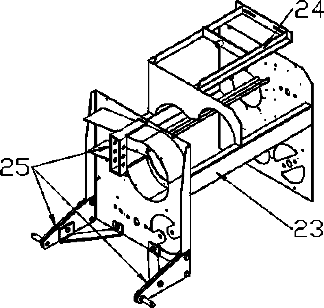
The invention relates to agricultural machinery, in particular to a design method and a device applicable to a corn sheller; the device comprises five parts, i.e. power transmission mechanisms, a threshing mechanism, a conveying mechanism, an impurity removing mechanism and a frame, and is characterized in that a drum of the threshing mechanism is provided with a screen hole, and the longitudinal direction of the screen hole is longer than the horizontal direction thereof; the power transmission mechanisms are arranged on both sides of the frame; the conveying mechanism comprises a pushing device and an elevating device, the pushing device is arranged on the lower side of the frame, the elevating device is arranged on one side of the frame, and the threshing mechanism and the impurity removing mechanism are fixed on the frame; each power transmission mechanism comprises a power access shaft head and a power access wheel; and when the power access shaft head serves as a power access point, the power access shaft head is connected with a power output PTO, a diesel engine or a motor in a transmission way. The invention not only has high efficiency and high purification to dry corn with skin or wet corn with skin, but also has simple structure, and can be combined with any power source.

Description

technical field [0001] The invention relates to agricultural machinery, in particular to a design method and device for a corn thresher. Background technique [0002] Although the known patent 02145589.9 corn threshing machine has high threshing cleanliness, the production efficiency is low due to the slow separation speed of granulation, and the original patent is more suitable for threshing dry corn with or without husk and threshing wet corn without husk. The threshing separation rate and clarity rate of wet corn with skin are affected. The original model can only be connected to the power output of the belt, and the improved model can be connected to PTO and other power outputs. At the same time, the spikes and concave plates of the original model The sieve, the main roller and the sieve hole have been improved to further improve the production efficiency, and the front movable slide plate, the rear fixed slide plate and the three-point suspension seat have been added. ...

Claims


Application Information

Patent Timeline
Patent Type & Authority Applications(China)
IPC IPC(8): A01F11/06A01F12/18
Inventor 袁毅
Owner 袁毅
Why Eureka
Eureka Blog
Learn More