Eureka AIR delivers breakthrough ideas for toughest innovation challenges, trusted by R&D personnel around the world.

Pan and tilt camera with sound identification and positioning function

A PTZ camera and voice recognition technology, applied in speech recognition, voice analysis, image communication and other directions, can solve the problems of the acquisition and processing of sound information that cannot be monitored on the scene, the transmission of sound information by the monitoring center, and the inability of PTZ cameras to collect, etc. To achieve the effect of solving the problem of picking up the sound at a short distance, improving work efficiency and enhancing functions

Inactive Publication Date: 2010-07-07
TIANJIN YAAN TECH CO LTD
View PDF0 Cites 53 Cited by
  • Summary
  • Abstract
  • Description
  • Claims
  • Application Information

AI Technical Summary

Problems solved by technology

Existing PTZ cameras usually can only collect on-site video information. However, in the actual monitoring process, many abnormal events are difficult to find through video information. For example, abnormal sounds, as a typical feature of abnormal events, cannot be detected by cameras. Acquisition, traffic accidents, dangerous calls for help, explosions and fights and other events are accompanied by very typical abnormal sounds; in addition, many anti-theft devices now emit alarm sounds under abnormal circumstances, but PTZ cameras cannot collect these sounds signals, and cannot transmit corresponding sound information to the monitoring center. Therefore, the existing PTZ cameras cannot collect and process the sound information of the monitoring site, thus affecting the monitoring effect.

Method used


Image

  • Pan and tilt camera with sound identification and positioning function
  • Pan and tilt camera with sound identification and positioning function
  • Pan and tilt camera with sound identification and positioning function

Examples


Embodiment Construction

[0017] Embodiments of the present invention are described in further detail below in conjunction with the accompanying drawings:

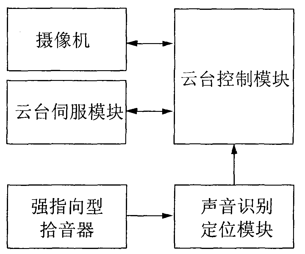
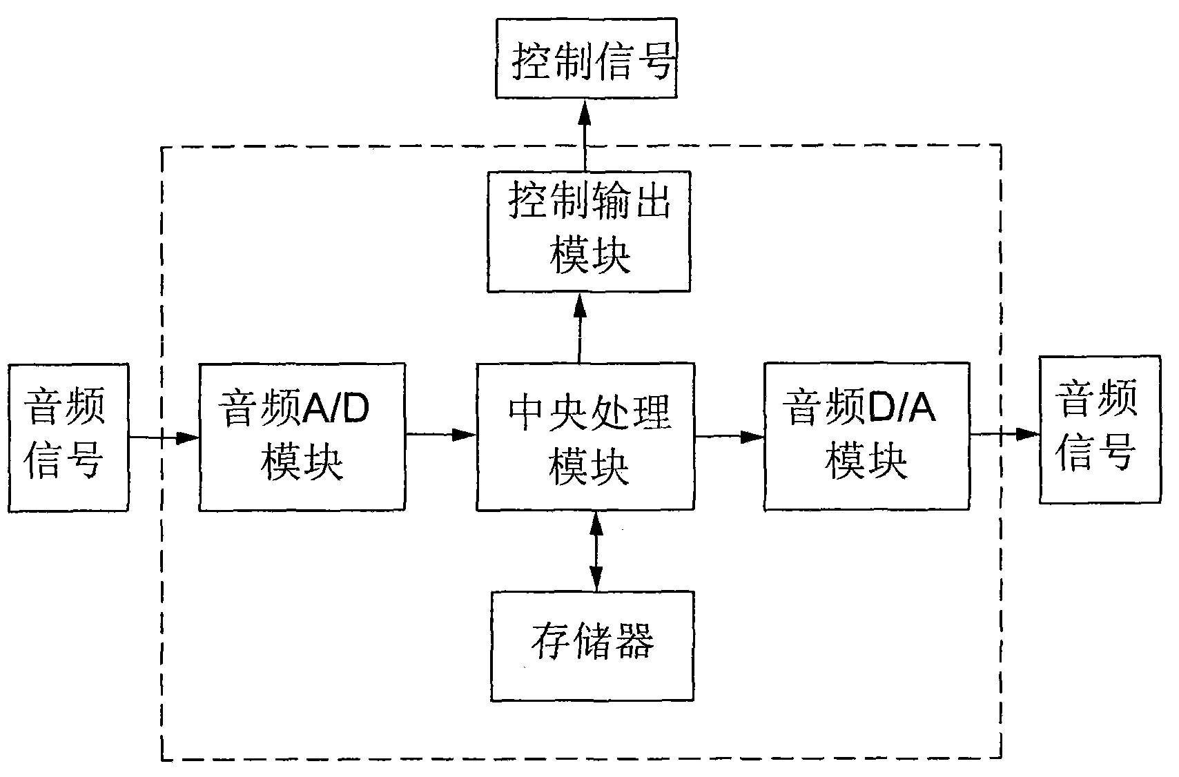
[0018] A kind of PTZ camera with sound recognition and positioning function, such as figure 1 As shown, it includes a camera, a pan / tilt servo module, a pan / tilt control module, a strong directional pickup and a voice recognition and positioning module. One output end of the identification and positioning module is connected to the pan-tilt control module, which is respectively connected to the camera and the pan-tilt servo module, and the other output end of the voice identification and positioning module is connected to the monitoring center. The strong directional pickup is fixed on the PTZ camera and the direction of the strong directional pickup is the same as the shooting direction of the camera, and the strong directional pickup can rotate together with the PTZ camera. The circuit structure of the sound recognition positioning module is com...


PUM


Abstract

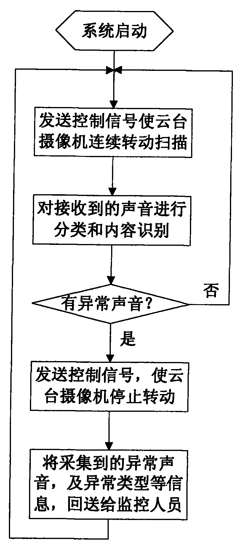
The invention relates to a pan and tilt camera with a sound identification and positioning function, which comprises a camera, a pan and tilt servo module and a pan and tilt control module, and the pan and tilt control module is respectively connected with the camera and the pan and tilt servo module. The pan and tilt camera has the following main technical characteristics that: the input end of the pan and tilt control module is connected with a sound identification and positioning module, and the input end of the sound identification and positioning module is connected with a highly directional sound pickup fixed on the pan and tilt camera. The design of the pan and tilt camera is reasonable, and the pan and tilt camera can identify and position the sound of a monitored site; when abnormal sound occurs, the pan and tilt camera can be controlled to aim at the direction of the sound source and shoot in order to timely acquire the video of an abnormal incident, and can send alarm information on the abnormal sound and the like to a monitoring center; the sound pickup distance is increased, the sound pickup effect are improved, the efficiency of capturing sound and other abnormal incidents is increased, and thereby the working efficiency of monitoring personnel can be increased.

Description

technical field [0001] The invention belongs to the field of security monitoring, in particular to a pan-tilt camera with voice recognition and positioning functions. Background technique [0002] At present, on-site monitoring through cameras has become one of the most important monitoring methods in the field of security monitoring. The most commonly used monitoring equipment is a PTZ camera with a PTZ servo device. The PTZ camera can adjust the shooting direction according to the command of the monitoring center, so as to shoot different areas of the monitoring site and send the video data back to the monitoring center for monitoring personnel to monitor. Analyze the situation on site. Existing PTZ cameras usually can only collect on-site video information. However, in the actual monitoring process, many abnormal events are difficult to find through video information. For example, abnormal sounds, as a typical feature of abnormal events, cannot be detected by cameras. A...

Claims


Application Information

Patent Timeline
IPC IPC(8): H04N5/225H04N5/232G10L15/00
Inventor 权立伟
Owner TIANJIN YAAN TECH CO LTD
Why Eureka
Eureka Blog
Learn More