
Pair surface self-adaption focusing method for radio telescope

A radio telescope, self-adaptive technology, applied in the direction of electrical components, antenna supports/mounting devices, antennas, etc., can solve problems such as changes in antenna efficiency, changes in focal length, flow rate of the source of observation objects or decrease in the accuracy of intensity data, and achieve strength The effect of stability improvement

Inactive Publication Date: 2010-07-07
ZIJINSHAN ASTRONOMICAL OBSERVATORY CHINESE ACAD OF SCI
View PDF5 Cites 5 Cited by
  • Summary
  • Abstract
  • Description
  • Claims
  • Application Information

AI Technical Summary

Problems solved by technology

[0004] The purpose of the present invention is to overcome the defects that the existing antenna panel deforms with temperature, resulting in focal length changes, antenna efficiency changes, the data accuracy of the flow or intensity of the observed object source, and the lack of determination of the focal length variation under conventional circumstances, and provides a radio telescope The sub-surface adaptive focusing method of

Method used


Image

  • Pair surface self-adaption focusing method for radio telescope
  • Pair surface self-adaption focusing method for radio telescope
  • Pair surface self-adaption focusing method for radio telescope

Examples


Embodiment 1

[0016] The subsurface self-adaptive focusing method of the radio telescope comprises the following steps:

[0017] (1) Install a temperature sensor on the antenna

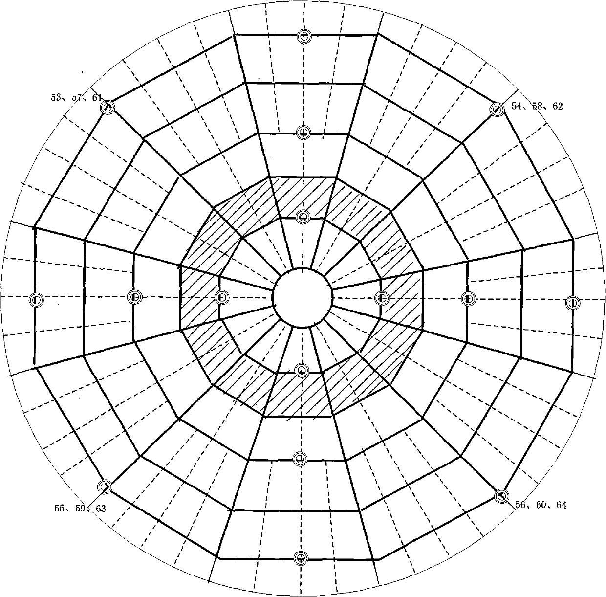
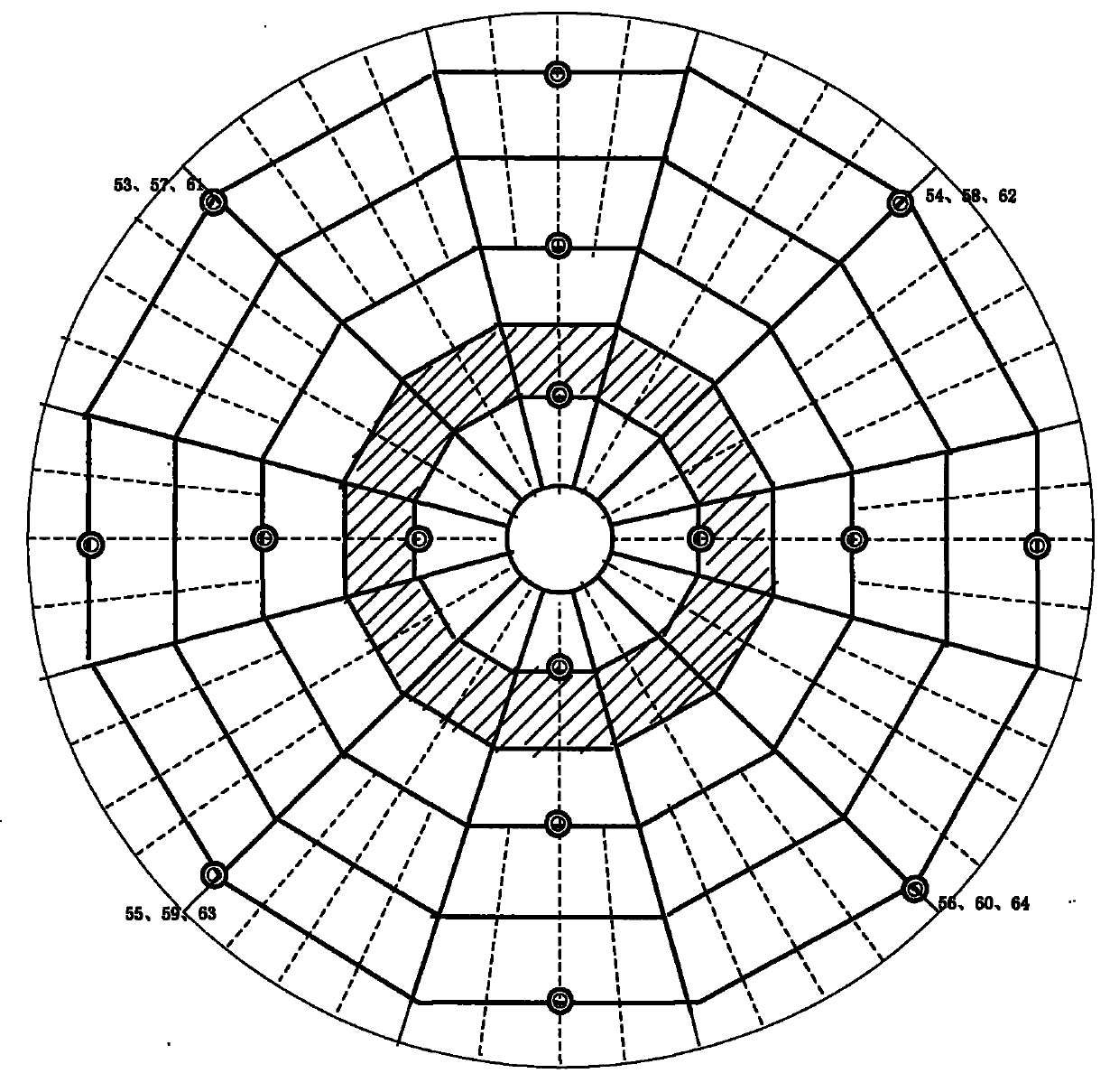
[0018] Install temperature sensors below the antenna panel and on the upper and lower sides of the back frame. The installation positions of the temperature sensors should be evenly distributed. In the present invention, the temperature sensors use TDC temperature sensors. Installation location such as figure 1 As shown in the distribution diagram of temperature sensors on the panel and the back frame, there are 3 sensors at each position, which are respectively located on the panel, the upper side of the back frame, and the lower side of the back frame.

[0019] (2) Use the astronomical method to adjust the longitudinal focus of the secondary surface:

[0020] On the basis of active control (that is, gravity deformation correction control), the auxiliary surface is translated in the Z direction (closer to or awa...


PUM


Abstract

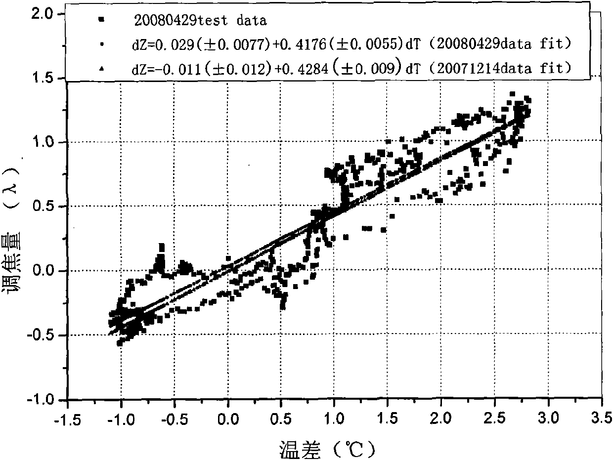
The invention relates to a pair surface self-adaption focusing method for a radio telescope. The method comprises the following steps of: arranging temperature sensors on a panel and a back frame of an antenna; performing pair surface longitudinal focusing by an astronomical method to record focusing information, wherein the focusing information comprises the focusing amount fitted by each turn of focusing, time observed at the point corresponding to the maximum of the source strength in each turn, the position of the antenna and the temperature value of each temperature sensor; according to the recorded information during focusing, analyzing the rule of the focusing amount and the temperature and the rule of the focusing amount and the temperature difference between the panel and the back frame to obtain the relationship between the focusing amount and the average temperature difference of the panel and the back frame; and performing self-adaption focusing by a pair surface control program based on the relationship obtained from the previous step, namely, according to the temperature difference measured by the temperature sensor and the relationship between the focusing amount and the temperature difference of the panel and the back frame, calculating the pair surface focusing amount in real time, correcting the pair surface in real time to make the pair surface at a proper position.

Description

technical field [0001] The invention relates to the field of astronomical observation, in particular to an adaptive focusing method for a secondary surface of a radio astronomical telescope. Background technique [0002] The focal length of a large-aperture radio telescope operating in a natural environment will change with the change of the ambient temperature. The change of the focal length may cause a significant change in the imaging quality. The method of adjusting the sub-surface can be used to compensate for the focal length change. Some radio telescopes use Focusing through a radio source with a good signal-to-noise ratio every once in a while, find a good side surface position, and then observe the method. This method is limited by the focusing source. Sometimes there is no suitable source for focusing, and it is a waste of time. . [0003] The antenna of the 13.7m radio telescope uses an aluminum back frame with large thermal expansion, which is a low-cost antenna...

Claims


Application Information

Patent Timeline
Patent Type & Authority Applications(China)
IPC IPC(8): H01Q1/12H01Q19/10
Inventor 杨戟孙继先逯登荣李阳
Owner ZIJINSHAN ASTRONOMICAL OBSERVATORY CHINESE ACAD OF SCI
Learn More