Eureka AIR delivers breakthrough ideas for toughest innovation challenges, trusted by R&D personnel around the world.

LED (light emitting diode) lamp unit and LED combined lamp

A technology of LED lamps and units, applied in damage prevention measures of lighting devices, lighting and heating equipment, point light sources, etc., to achieve the effects of simple and light structure, convenient connection and installation, and good lighting and decorative effects

Inactive Publication Date: 2010-07-07
CE LIGHTING
View PDF0 Cites 10 Cited by
  • Summary
  • Abstract
  • Description
  • Claims
  • Application Information

AI Technical Summary

Problems solved by technology

In the field of LED lamps, there has not yet appeared a lamp with flexible application, various combinations and easy replacement

Method used


Image

  • LED (light emitting diode) lamp unit and LED combined lamp
  • LED (light emitting diode) lamp unit and LED combined lamp
  • LED (light emitting diode) lamp unit and LED combined lamp

Examples


Embodiment 1

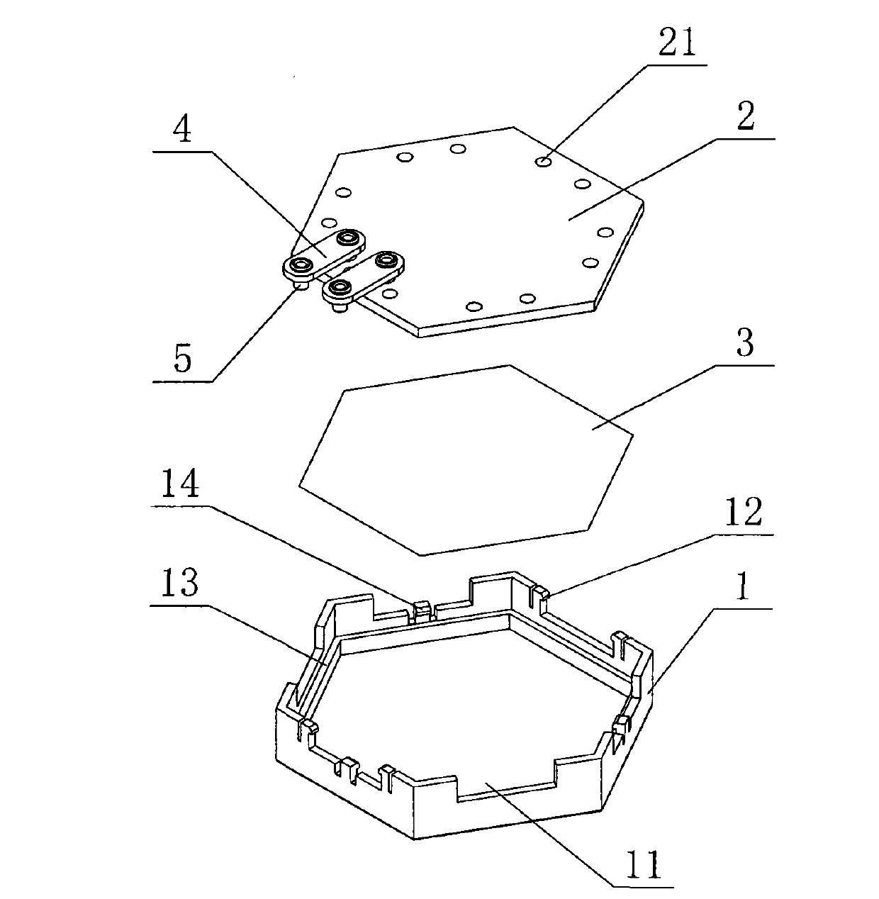
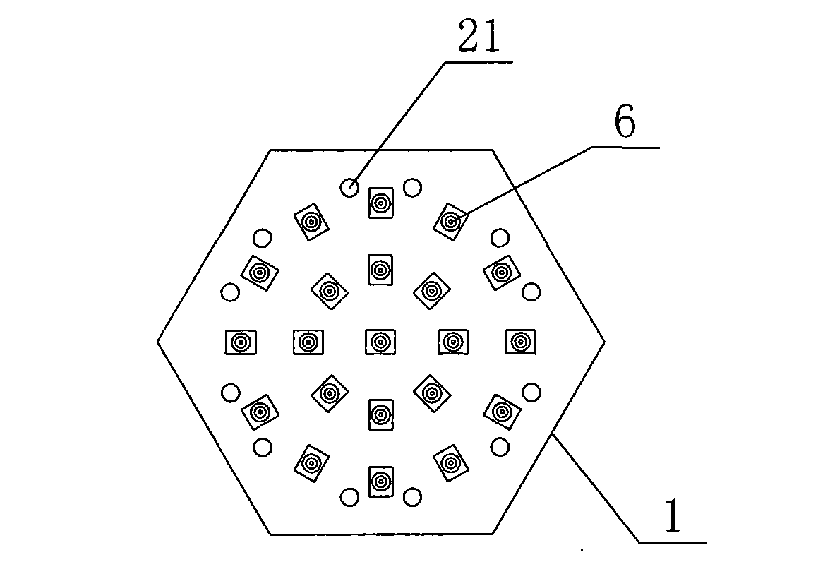
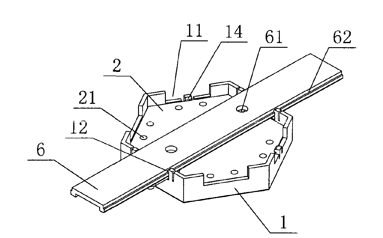
[0027] Such as figure 1 , figure 2 , image 3 , Figure 4 As shown, the LED combination lamp of this embodiment is a low-voltage LED combination lamp, which includes a mounting board 6 and four LED lamp units. The LED lamp unit includes a housing 1, a circuit board 2, a film lens 3, two Pairs of conductive connecting pieces 4, the front of the circuit board 2 is provided with several LED6, the housing 1, the circuit board 2 are regular hexagonal, certainly can be other polygons, the circuit board 2 Embedded in the housing 1, each side of the housing 1 is provided with a relief groove 11 for the conductive connecting piece 4 to pass through, and a pair of opposite side edges of the relief groove 11 There is a snap tongue 12 at the place, the mounting plate 6 is provided with a fixing hole 61 and a snap edge 62, the snap tongue 12 is matched with the snap edge 62, and the bottom of the housing 1 is provided with an edge 13. The side of the housing 1 is provided with a block...

Embodiment 2

[0029] Such as figure 1 , figure 2 , Figure 5 As shown, the difference between this embodiment and Embodiment 1 is that: the LED combination lamp of this embodiment includes seven LED lamp units, the LED combination lamp is in a honeycomb shape, and the mounting plate 6 can be arranged according to the LED lamp As for the combination of the unit body, three mounting plates 6 are selected.

[0030] The remaining features of this embodiment are the same as those of Embodiment 1.

Embodiment 3

[0032] Such as figure 1 , figure 2 , Image 6 As shown, the difference between this embodiment and Embodiment 1 is that: the LED combined lamp of this embodiment includes nine LED lamp units, the LED combined lamp is wave-shaped, and the mounting plate 6 can be adjusted according to the LED lamp. As for the combination of the unit body, three mounting plates 6 are selected.

[0033] The remaining features of this embodiment are the same as those of Embodiment 1.


PUM


Abstract

The invention discloses an LED (light emitting diode) lamp unit having simple and light structure, abundant combination change, flexible application, convenient connection and mounting and various illumination and decoration effects and a combined lamp. The LED combined lamp comprises a mounting plate (6) and the LED lamp units, wherein each LED lamp unit comprises a polygonal shell (1), a circuit board (2) and a conductive connecting piece (4); LEDs (6) are arranged on each circuit board (2), and the circuit board (2) is embedded in a shell (1); all the edges of each circuit board (2) are respectively provided with two conductive jacks (21) used as anode and cathode terminals of each LED lamp unit; both ends of each conductive connecting piece (4) are fixed with a conductive rivet (5), and the conductive rivets (5) are embedded in the anode and cathode conductive jacks (21) and tightly matched with the conductive jacks (21); adjacent LED lamp units are conductively connected through two conductive connecting pieces (4) and the conductive rivets (5) at both ends of the conductive connecting pieces (4); and the LED lamp units are fixedly connected with the mounting plate (6).

Description

technical field [0001] The invention relates to an LED lamp unit body and an LED combination lamp comprising the LED lamp unit body. Background technique [0002] Lamp is a kind of lighting equipment, which also has the function of decoration. Most of the current lamps are independent, and there are few ways to combine them through units. Their structures are relatively bulky, their flexibility is not enough, and their combination changes are not rich enough. With the development of LED semiconductor lighting, LEDs are currently being used more and more widely as light sources for lamps. In the field of LED lamps, there has not yet appeared a lamp with flexible application, various combinations, and easy replacement. Contents of the invention [0003] The technical problem to be solved by the present invention is to overcome the deficiencies of the prior art, and provide an LED lamp unit and an LED combination lamp with simple and light structure, rich combination transf...

Claims


Application Information

Patent Timeline
Patent Type & Authority Applications(China)
IPC IPC(8): F21S2/00F21V23/00F21V15/02F21V5/04F21Y101/02
Inventor 魏永纲王晓锋
Owner CE LIGHTING
Why Eureka
Eureka Blog
Learn More