
Flat knitting machine for knitting cylindrical knitted fabric and method of knitting cylindrical knitted fabric

A technology for knitted fabrics and tubular shapes, which is applied in the field of flat knitting machines for knitting tubular knitted fabrics and the field of knitting tubular knitted fabrics. It can solve the problems of easy penetration of material liquid into the interior and uneven thickness.

Active Publication Date: 2010-07-07
SHIMA SEIKI MFG LTD
View PDF2 Cites 6 Cited by
  • Summary
  • Abstract
  • Description
  • Claims
  • Application Information

AI Technical Summary

Problems solved by technology

Coating of rubber materials etc. is carried out by immersing in the material liquid, but when the coil pitch at the boundary portion is enlarged, the material liquid tends to permeate into the inside
In addition, when the size of the pile is different, the thickness of the material liquid adhesion will be uneven

Method used


Image

  • Flat knitting machine for knitting cylindrical knitted fabric and method of knitting cylindrical knitted fabric
  • Flat knitting machine for knitting cylindrical knitted fabric and method of knitting cylindrical knitted fabric
  • Flat knitting machine for knitting cylindrical knitted fabric and method of knitting cylindrical knitted fabric

Examples


Embodiment Construction

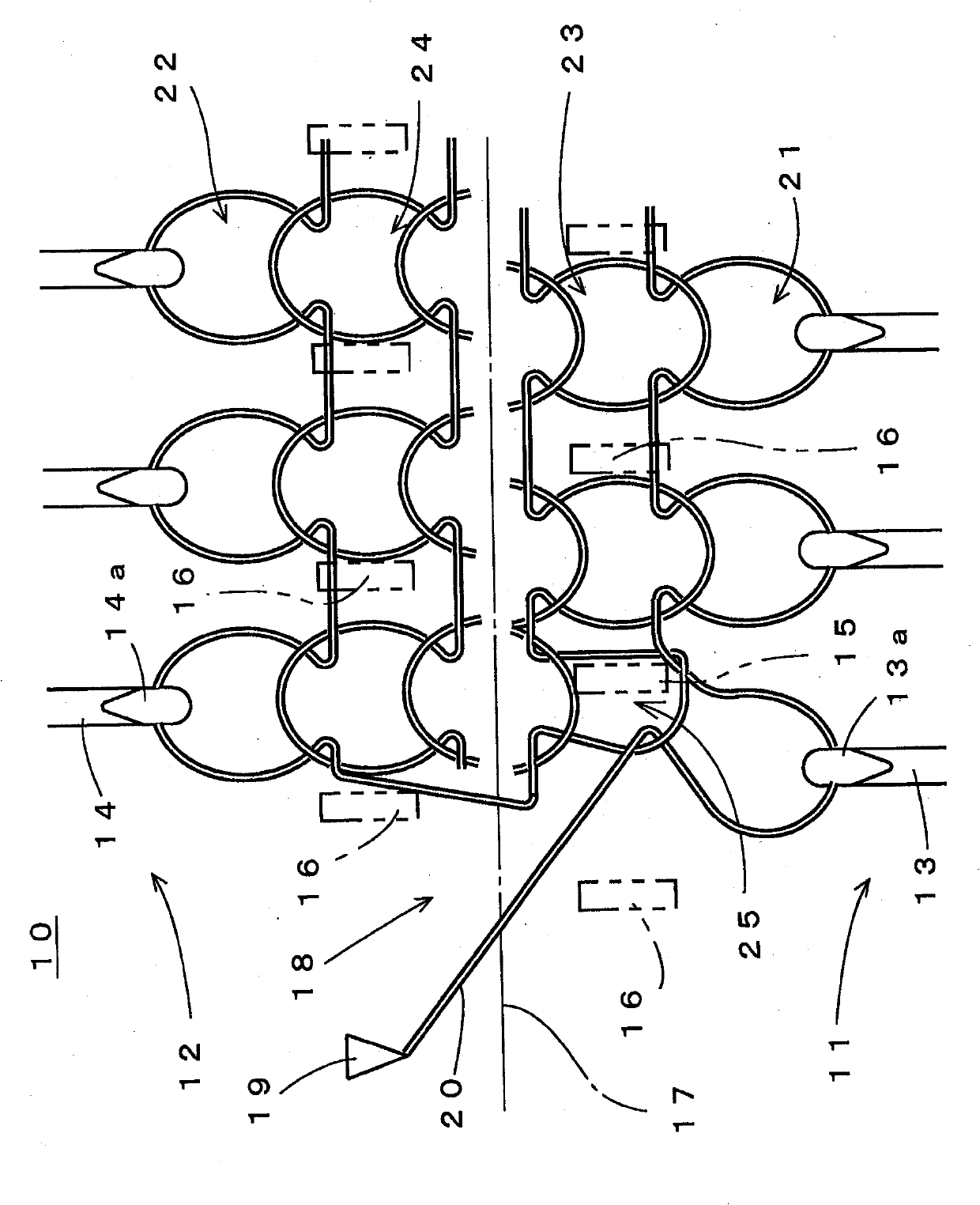
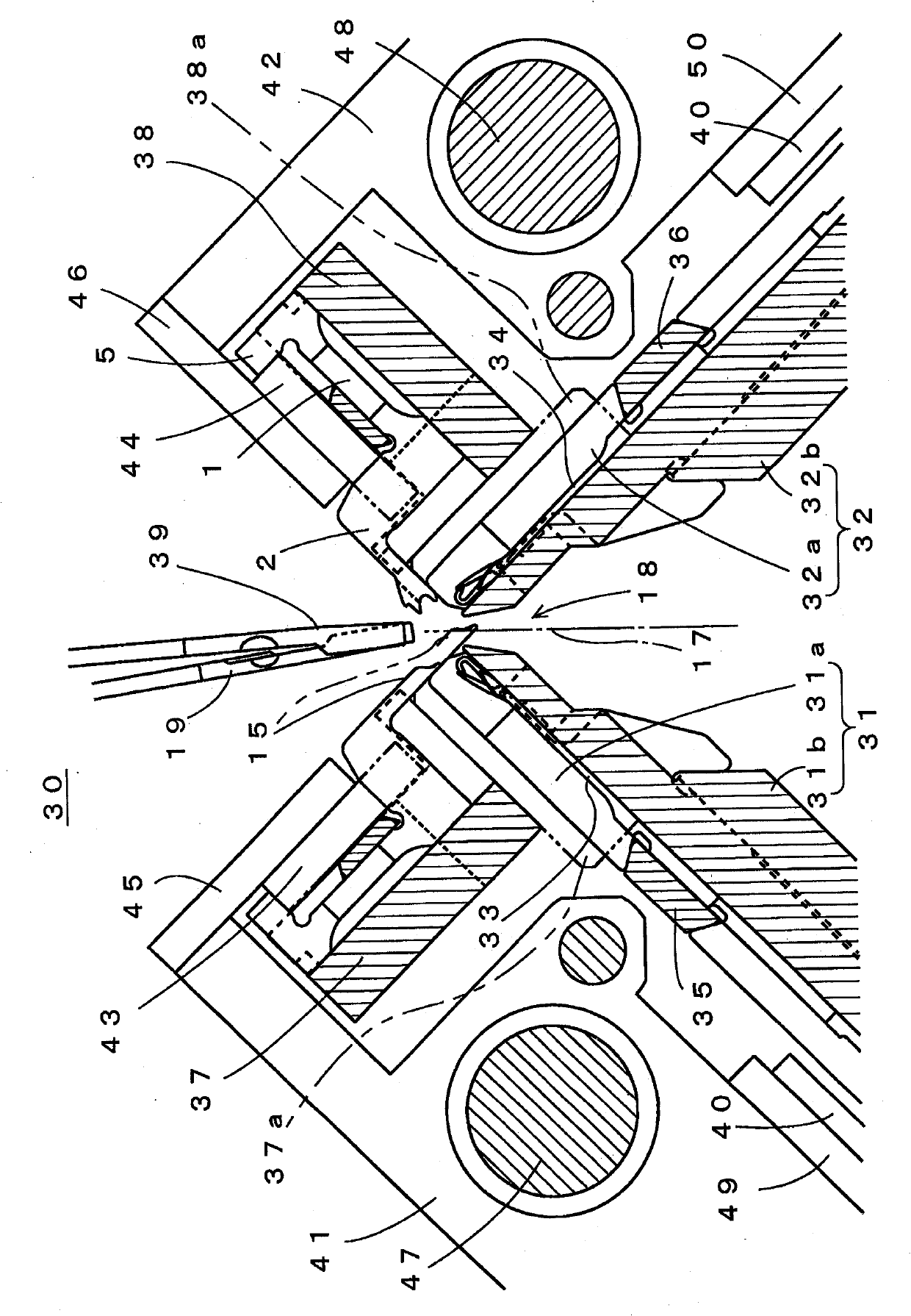
[0048] figure 1 The main part of the structure of the flat knitting machine 10 which concerns on one Embodiment of this invention is shown typically. The flat knitting machine 10 has a front needle bed 11 and a rear needle bed 12 . On the front needle bed 11 and the rear needle bed 12, a plurality of knitting needles 13 and 14 are arranged in a row, respectively. Hooks 13a and 14a are provided at the tips of the respective knitting needles 13 and 14 . The knitting needles 13 of the front needle bed 11 and the knitting needles 14 of the rear needle bed 12 are arranged so that the positions where they meet are shifted. The tubular knitted fabric is knitted by feeding the yarn in such a way that the knitting yarn is looped in a certain direction. For example, in the case of knitting a tubular knitted fabric by feeding clockwise yarn, the knitting needles 13 of the front needle bed 11 are fed from right to left in the figure to the knitting needles 14 of the rear needle bed 12...


PUM


Abstract

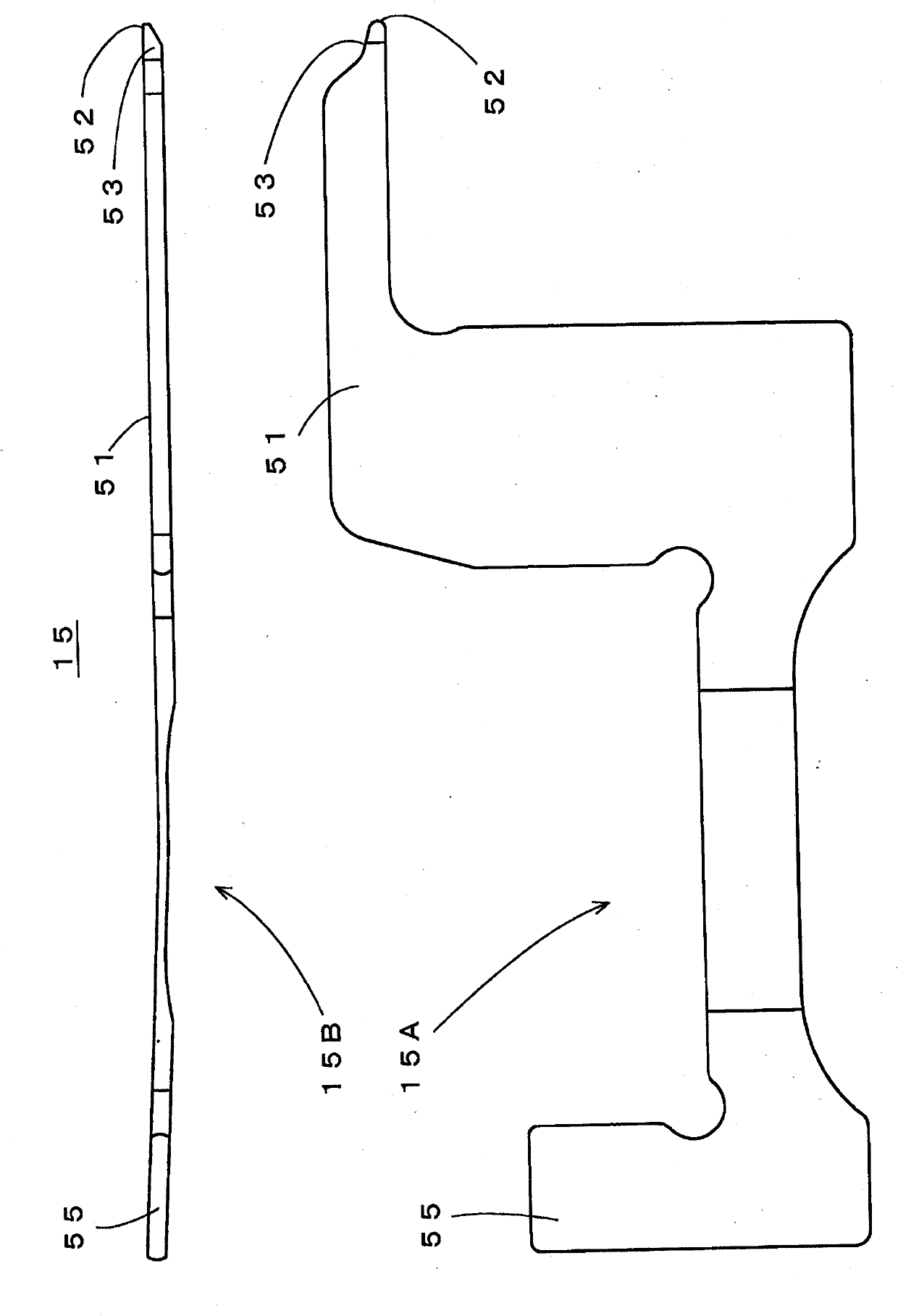
The present invention provides a flat knitting machine for knitting cylindrical knitted fabric having un-conspicuous boundaries and a method of knitting cylindrical knitted fabric. The knitting width is reduced when knitting needles (13, 14) cast off and are transferred to a mouth (18), therefore an old coil (25) from a knitting needle (13) of the end of the knitting width is shrank in a mode of being bias from a new coil (21) toward the inner side of the knitting width, if the position of an expansion component (15) is arranged to be identical with that of the old coil (25), the frontend of the expansion component (15) is capable of entering into the mouth (18) and is inserted into the old coil (25), if the shape of the frontend of the expansion component (15) is designed to be a taper shape which is thin and has a small variation of diameter, the frontend can be easily inserted into the old coil (25) for expanding the old coil (25) gradually, and even through being reduced, the sizeof a new coil (21) finally formed by reversing the direction of supplying knitting yarn (20) can be recovered through the expending of the expansion component (15) by transferring the front end of the expansion component to the mouth (18) to form the old coil (25) after round knitting.

Description

technical field [0001] The present invention relates to a flat knitting machine for tubular knitted fabric knitting in which a knitted fabric is tubularly knitted by a flat knitting machine having a pair of needle beds facing each other with a gap between them, and a knitting method for a tubular knitted fabric. Background technique [0002] Conventionally, a tubular knitted fabric is knitted by tubular knitting in a flat knitting machine having needle beds in the front and rear across the nip. In the tubular knitting, the knitting yarn is fed in a certain direction across two needle beds, and a plain knitted fabric is knitted on each needle bed. The tubular knitted fabric produced by tubular knitting is used for, for example, gloves, socks, and the like. [0003] In a general-purpose flat knitting machine having a stitch transfer function for transferring stitches between needle beds, one side knitted fabric can be knitted using two needle beds, respectively, and both side...

Claims


Application Information

Patent Timeline
Patent Type & Authority Applications(China)
IPC IPC(8): D04B7/32D04B15/06D04B15/10D04B15/36
CPCD04B1/26D04B9/42D04B9/44D04B15/06
Inventor 田村彰智
Owner SHIMA SEIKI MFG LTD
Learn More