
Sludge dehydration treatment technology

A treatment process and sludge dewatering technology, applied in dewatering/drying/concentrating sludge treatment, etc., can solve the problems of high solid content in the separation liquid, low solid recovery rate, and unclean filter cloth cleaning, so as to improve the concentration effect. Effect

Active Publication Date: 2010-07-07
四川蓉信开工程设计有限公司
View PDF0 Cites 19 Cited by
  • Summary
  • Abstract
  • Description
  • Claims
  • Application Information

AI Technical Summary

Problems solved by technology

[0015] In the current sludge dewatering process, in the process of treating excess activated sludge, the main problems are high moisture content of the dehydrated mud cake, low mud cake output, large amount of dosing, unclean filter cloth cleaning, high solid content of the separation liquid, Problems such as low solid recovery rate

Method used


Image

  • Sludge dehydration treatment technology
  • Sludge dehydration treatment technology
  • Sludge dehydration treatment technology

Examples


Embodiment 1

[0038] Embodiment 1 The intermittent sludge thickening tank adopted by the present invention

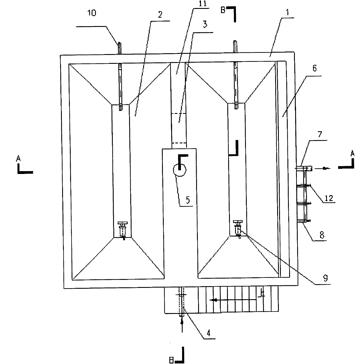
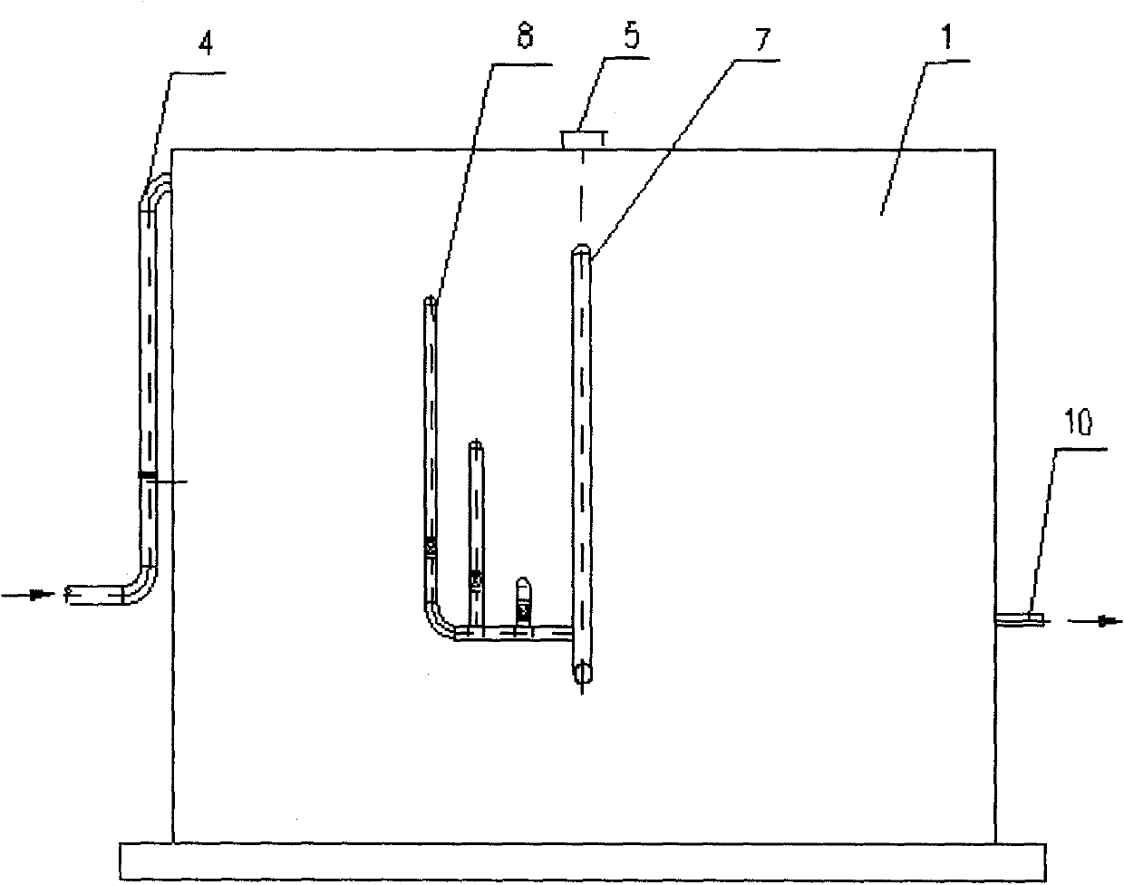
[0039] Such as figure 1 As shown, a kind of intermittent sludge thickening tank capable of uniform discharge of the present invention includes a tank body 1, a sludge bucket 2, a communication port 3, a mud inlet pipe 4, a center pipe 5, an overflow weir 6, a supernatant Liquid drain pipe 8, submersible mixer 9 and mud discharge pipe 10. The designed solid flux of the concentration tank is 60kg / (m 2 .d). The pool body 1 is a reinforced concrete structure of a cube, and its structural size is 9000×9000×6000 (mm); the interior of the pool body 1 is divided into two cuboids by dikes 11, and the ratio of the length (L) and width (H) of the cuboid is L / H=2; the bottom of each cuboid is the sludge bucket 2, so that the bottom of the pool body 1 forms a "W"-shaped double bucket structure, the plane size of the bottom of the single bucket is 1352×6100 (mm), and the four sides of the slud...

Embodiment 2

[0046] figure 1 It is a schematic process flow diagram of the present invention. The engineering example involved in the present invention is the sludge three-time concentration + mechanical dehydration treatment process, and the designed residual sludge treatment capacity is 70m 3 / h (not including the sludge return flow part), the water content of the imported sludge of the treatment process is 99.4% to 99.7%, and the continuous gravity concentration tank A involved in this embodiment utilizes the structure of the biochemical secondary settling tank and is placed in the secondary settling tank A sludge discharge control valve is added to the sludge discharge pipeline to ensure that the sludge concentration discharged from the secondary settling tank is controlled within a certain range. The structural size of the continuous gravity concentration pool A is 34×3.6m, the sludge enters the continuous gravity thickening tank A, and after 2-3 hours of thickening, the moisture c...


PUM

PropertyMeasurementUnit
Diameteraaaaaaaaaa

Abstract

The invention relates to a sludge dehydration treatment technology which includes the steps as follows: residual active sludge is treated for concentration sequentially in a continuous gravity concentration tank and an intermittent sludge concentration tank, then put in a chemical conditioning tank and guided into a tumbling centrifugal concentrator for further concentration after being chemically conditioned, and finally put into a belt filter press to be dehydrated to become sludge cake. The sludge dehydration treatment technology of the invention aims at the residual active sludge property characteristics to strengthen the concentration effect before mechanical dehydration and has the advantages of little addition dosage in dehydration, sludge cake chickening, low moisture content in sludge cake, easy washing of filtration fabric not stuck by sludge, low solid content in separation medium, and high solid recovery rate.

Description

technical field [0001] The invention relates to a sludge dehydration treatment process, which is mainly suitable for volume reduction treatment of excess activated sludge in sewage treatment plants, and belongs to the field of sludge treatment in sewage treatment plants. Background technique [0002] Sewage treatment plants mainly include primary sedimentation sludge, residual activated sludge and chemical sludge. The moisture content of the sludge is generally very high. The moisture content of the sludge in the primary sedimentation tank is between 95% and 97%, the residual activated sludge is above 99.2%, and the moisture content of the chemical sludge is above 99.5%. The remaining activated sludge produced by sewage treatment plants generally accounts for more than 80% of the total sludge output. Activated sludge is mainly composed of four parts: active microbial populations with metabolic functions; microbial endogenous respiration and self-oxidized residues; refractor...

Claims


Application Information

Patent Timeline
IPC IPC(8): C02F11/14
Inventor 王光鲍阳阳
Owner 四川蓉信开工程设计有限公司
Learn More