Physical amount change history recording method, its program, flow rate measuring device, and fluid supply system

A flow measurement device and physical quantity technology, applied in the direction of measuring flow/mass flow, measuring device, liquid/fluid solid measurement, etc., to achieve the effects of reducing storage capacity, improving calculation speed and recognition accuracy, and simplifying calculations

Active Publication Date: 2010-06-30
PANASONIC CORP
View PDF3 Cites 3 Cited by
  • Summary
  • Abstract
  • Description
  • Claims
  • Application Information

AI Technical Summary

Problems solved by technology

[0003] In the above-mentioned gas meter 1, the change in the differential value between the instantaneous flow output from the flow measurement unit 3 is continuously calculated, and the change in the operating state of the gas appliance is recognized based on the change amount; registered data and measurement The gas flow changes (difference values) are compared with each other, and identification of the working gas appliances 13, 14, and 15 becomes possible

Method used


Image

  • Physical amount change history recording method, its program, flow rate measuring device, and fluid supply system
  • Physical amount change history recording method, its program, flow rate measuring device, and fluid supply system
  • Physical amount change history recording method, its program, flow rate measuring device, and fluid supply system

Examples


Embodiment Construction

[0040] Embodiments of the present invention will be described with reference to the drawings.

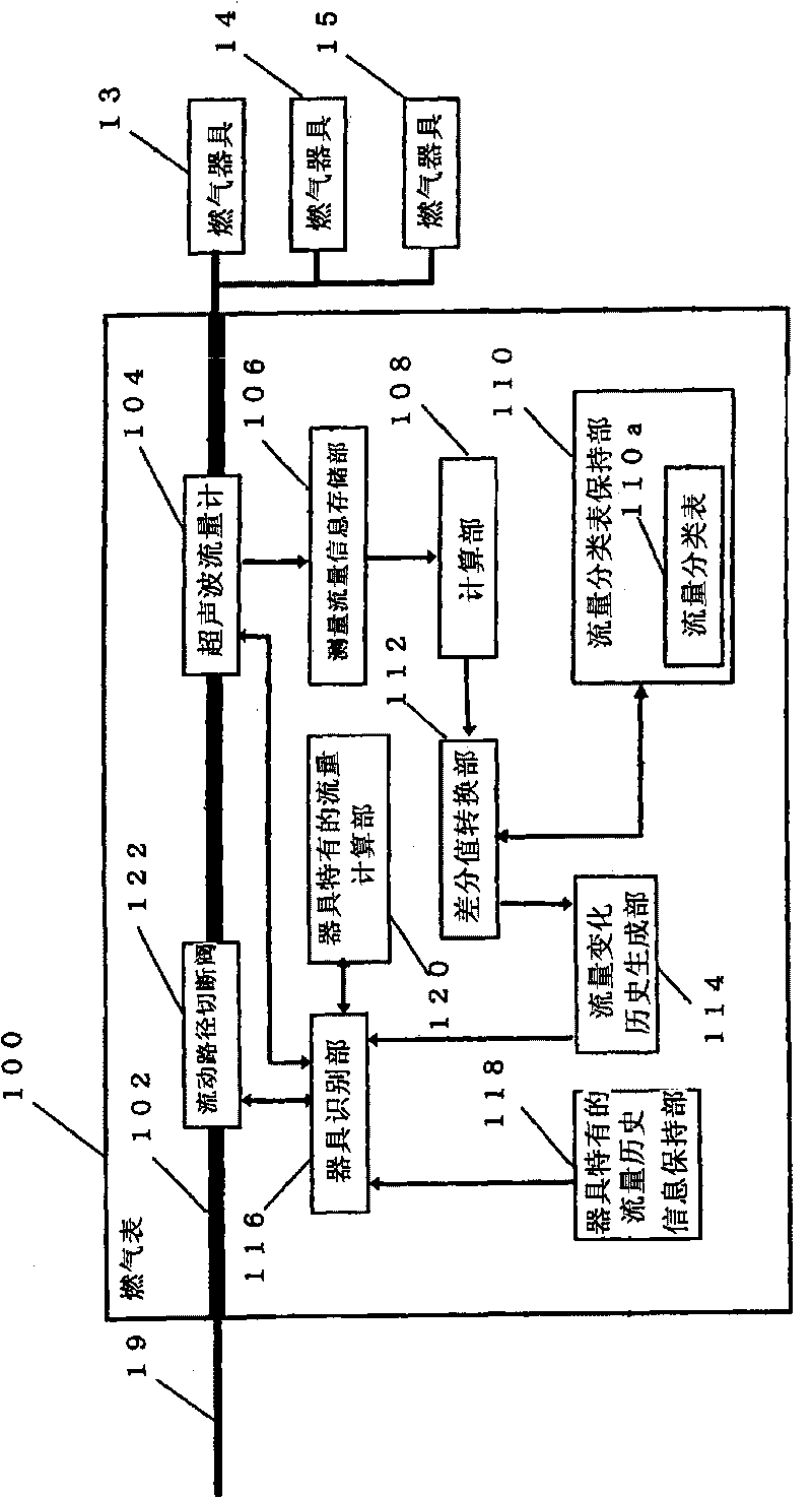
[0041] figure 1 It is a block diagram of a gas meter as a flow measuring device (physical quantity measuring device) in an embodiment of the present invention.

[0042] figure 1 Among them, the gas meter 100 includes: a flow path 102, an ultrasonic flowmeter 104 as a flow measurement unit, a measured flow information storage unit 106, a calculation unit 108, a flow classification table storage unit 110, a differential value conversion unit 112, and a flow change history generation unit. 114 , an appliance identification unit 116 , and an appliance-specific flow history information storage unit 118 . The gas meter 110 further includes a flow path shutoff valve 122 on the flow path 102 for shutting off gas in an emergency or the like.

[0043] The ultrasonic flowmeter 104 emits ultrasonic waves at given time intervals (for example, two seconds, etc.) to gas as a fluid flowing in ...


PUM


Abstract

When providing an instrument identification technique, it is possible to improve the calculation speed and the identification accuracy while reducing a necessary memory amount. A gas meter (100) includes an ultrasonic flowmeter (104) which measures a flow rate of a gas flowing in a flow channel (102) at a predetermined time interval and a calculation unit (108) which calculates a difference value between flow rates measured by the calculation unit (108) at a predetermined time interval. According to a flow rate division table (110a) containing a plurality of difference value divisions based on the difference values which are correlated to codes indicating the respective divisions, a difference value conversion unit (112) converts the calculated difference value into a code. Furthermore, according to a set of codes obtained at a predetermined time interval, a flow rate change history generation unit (114) generates a flow rate change history as a dummy expression of a gas flow rate change.

Description

technical field [0001] The present invention relates to a technique for correctly identifying phenomena by capturing changes in physical quantities such as fluid flow rates. Background technique [0002] For example, a gas meter has hitherto been available as a device for capturing changes in physical quantities and identifying phenomena. Patent Document 1 describes a gas meter for identifying work implements in a fluid piping system having a gas meter. The gas meter 1 in the document has: a flow measurement unit 3, which is placed in a flow path 6 connected to a domestic gas supply pipe, for measuring the gas flow at given time intervals; a calculation unit 4, which uses and a comparison and determination unit 7 for making a difference between the difference value calculated by the calculation unit 4 and the change determination value registered in the storage unit 5 Compare, and determine the change in the working status of each gas appliance, such as Figure 7 shown. T...

Claims


Application Information

Patent Timeline
Patent Type & Authority Applications(China)
IPC IPC(8): G01F3/22G01F15/06
CPCY04S20/32G01D4/002G01F1/66G01F15/002G01F15/068Y04S20/38Y02B90/241G01D2204/24Y04S20/30Y02B90/20
Inventor 岩本龙志
Owner PANASONIC CORP
Why Eureka
Try Eureka