
Driving device for light-emitting component

A technology of driving devices and light-emitting elements, which can be applied to instruments, static indicators, etc., and can solve problems such as uneven brightness of display panels

Inactive Publication Date: 2010-06-30
AU OPTRONICS CORP
View PDF0 Cites 16 Cited by
  • Summary
  • Abstract
  • Description
  • Claims
  • Application Information

AI Technical Summary

Problems solved by technology

Under the condition of the same data voltage, the brightness of each pixel circuit has a slight difference, resulting in uneven brightness on the display panel

Method used


Image

  • Driving device for light-emitting component
  • Driving device for light-emitting component
  • Driving device for light-emitting component

Examples


Embodiment Construction

[0048] In order to make the above-mentioned features and advantages of the present invention more comprehensible, the following specific embodiments are described in detail together with the accompanying drawings.

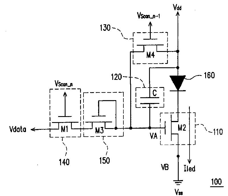
[0049] The following describes the embodiments of the present invention, and uses the light-emitting element and the driving device as the implementation of the pixel circuit in the display panel, so that those skilled in the art can better understand the spirit of the present invention. Please refer to figure 1 , figure 1 It is an equivalent circuit diagram illustrating the driving device 100 of the light emitting element 160 according to the first embodiment of the present invention. The driving device 100 for the light emitting element 160 includes a driving circuit 110 , a storage unit 120 , a reset circuit 130 , a first switch 140 and a compensation circuit 150 . The driving circuit 110 has a control terminal and a driving terminal, and the driving terminal ...


PUM


Abstract

The invention provides a driving device for a light-emitting component. The driving device comprises a driving circuit, a storage unit, a resetting circuit, a first switch and a compensating circuit, wherein the driving circuit determines a current on a driving end according to a voltage on a control end thereof; the storage unit is arranged for keeping the voltage on the control end of the driving circuit; the resetting circuit is arranged for providing a resetting voltage to the control end of the driving circuit during the resetting process; a first end of the first switch is arranged for receiving a data voltage; a control end of the first switch is arranged for receiving a scanning voltage; and the compensating circuit is connected between a second end of the first circuit and the control end of the driving circuit so as to transmit the data voltage provided by the first switch to the control end of the driving circuit. The driving current generated by the driving device for a light-emitting component is not affected by a critical voltage of a transistor so each pixel of the light-emitting component on a display panel can acquire a same luminance according to the data voltage.

Description

technical field [0001] The present invention relates to a driving device for a light-emitting element, and in particular to a driving device for a light-emitting element used in a pixel circuit. Background technique [0002] The information and communication industry has become the mainstream industry today, whether it is portable communication display products, home TVs or computer monitors, etc., are the focus of technological development. The flat-panel display is a communication interface for public information exchange, and its development is particularly important. [0003] At present, there are the following flat display technologies: liquid crystal display (Liquid Crystal Display, LCD), inorganic electroluminescent display (Electro-luminescent Display), light-emitting diode (Light-EmittingDiode, LED), organic light-emitting diode (organic light emitting diode, OLED), plasma display (Plasma Display Panel, PDP), vacuum fluorescent display (Vacuum Fluorescent Display) ...

Claims


Application Information

Patent Timeline
IPC IPC(8): G09G3/20G09G3/32G09G3/3258
Inventor 蔡宗廷
Owner AU OPTRONICS CORP
Learn More