Method for manufacturing optical waveguide by using azobenzene polymer
An azo polymer and optical waveguide technology, applied in the direction of optical waveguide and light guide, can solve the problems of narrow range of refractive index change, can not meet the requirements of waveguide device refractive index gradient change, not too much, etc., to achieve low price, The effect of eliminating reactive ion etching and avoiding the use of photoresist
- Summary
- Abstract
- Description
- Claims
- Application Information
AI Technical Summary
Benefits of technology
Problems solved by technology
Method used
Image
Examples
preparation example Construction
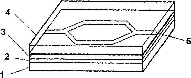
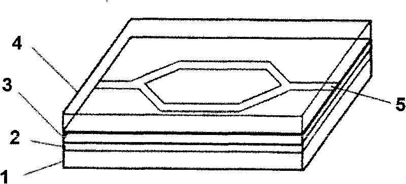
[0030] The method that the present invention proposes to make optical waveguide with azo polymer, the structural representation of the prepared optical waveguide is as follows figure 1 Shown, specific preparation method comprises the following steps:
[0031] (1) cleaning the substrate 1;
[0032] (2) Mix the epoxy resin prepolymer, isocyanate and N,N-dimethylformamide to obtain a first mixed solution. The mixing mass ratio is: epoxy resin prepolymer:isocyanate:N,N-dimethylformamide=1:0.3-0.9:3-9. The first mixed solution is spin-coated on the above-mentioned cleaned substrate, and dried at a temperature of 60-180° C. for 6-12 hours to obtain a lower cladding layer 2 with a thickness of 1.0-5.0 microns, wherein the epoxy resin The molecular structural formula of the prepolymer is:
[0033]
[0034] (3) Mixing the azo polymer, isocyanate and N,N-dimethylformamide to obtain a second mixed solution. The mixing mass ratio is: azo polymer: isocyanate: N, N-dimethylformamide ...
Embodiment 1
[0050] (1) Select silicon as the substrate material, use acetone, ethanol, and water for 15 minutes to sonicate, repeat twice, and finally blow dry with N2 gas for later use;
[0051] (2) Mix the epoxy resin prepolymer, isocyanate and N,N-dimethylformamide to obtain a first mixed solution. The mixing mass ratio is: epoxy resin prepolymer:isocyanate:N,N-dimethylformamide=1:0.6:6.4. The first mixed solution was spin-coated on the above-mentioned cleaned substrate, and dried at 60° C. for 12 hours to obtain a lower cladding layer with a thickness of 3.0 μm, wherein the molecular structural formula of the epoxy resin prepolymer is :
[0052]
[0053] (3) Azopolymer, isocyanate and N, N-dimethylformamide are mixed to obtain the second mixed solution, and the mass ratio of mixing is: azopolymer: isocyanate: N, N-dimethylformamide Amide=1:0.25:12, the second mixed solution is spin-coated on the above-mentioned lower cladding layer, and dried at 60°C for 12 hours to obtain a core...
Embodiment 2
[0060] (1) Select quartz glass as the substrate material, use acetone, ethanol, and water to sonicate for 15 minutes, repeat twice, and finally dry it with N2 gas for later use;
[0061] (2) Mix the epoxy resin prepolymer, isocyanate and N,N-dimethylformamide to obtain a first mixed solution. The mixing mass ratio is: epoxy resin prepolymer:isocyanate:N,N-dimethylformamide=1:0.6:6.4. The first mixed solution was spin-coated on the above-mentioned cleaned substrate, and dried at 60° C. for 12 hours to obtain a lower cladding layer with a thickness of 3.0 μm, wherein the molecular structural formula of the epoxy resin prepolymer is :
[0062]
[0063] (3) Azopolymer, isocyanate and N, N-dimethylformamide are mixed to obtain the second mixed solution, and the mass ratio of mixing is: azopolymer: isocyanate: N, N-dimethylformamide Amide=1:0.25:12, the second mixed solution is spin-coated on the above-mentioned lower cladding layer, and dried at 60°C for 12 hours to obtain a c...
PUM
| Property | Measurement | Unit |
|---|---|---|
| Thickness | aaaaa | aaaaa |
| Thickness | aaaaa | aaaaa |
| Thickness | aaaaa | aaaaa |
Abstract
Description
Claims
Application Information
 - R&D
- Intellectual Property
- Life Sciences
- Materials
- Tech Scout
- Unparalleled Data Quality
- Higher Quality Content
- 60% Fewer Hallucinations
Browse by: Latest US Patents, China's latest patents, Technical Efficacy Thesaurus, Application Domain, Technology Topic, Popular Technical Reports.
© 2025 PatSnap. All rights reserved.Legal|Privacy policy|Modern Slavery Act Transparency Statement|Sitemap|About US| Contact US: help@patsnap.com


