
Drive adjusting and loading platform of online detection device

A technology of testing equipment and loading platform, applied in the direction of measuring device, material analysis by optical means, instruments, etc., can solve the problems of full automation and efficiency discount, cumbersome sampling inspection, and inability to effectively complete the whole process of inspection, so as to ensure product quality. The effect of quality, saving human resources and improving efficiency

Inactive Publication Date: 2010-06-30
苏州德天光学技术有限公司
View PDF0 Cites 10 Cited by
  • Summary
  • Abstract
  • Description
  • Claims
  • Application Information

AI Technical Summary

Problems solved by technology

[0002] In the prior art, when detecting defects on PCB boards (printed circuit boards), it is necessary to remove finished or semi-finished PCB boards from the PCB board production line, and test them one by one on the testing equipment. This method is usually called offline. Operation, it is usually impossible to test every product with the offline detection operation method, but adopts the method of random inspection, which not only cannot fully and effectively control the product quality, but also the random inspection is cumbersome, and needs to be tested at each Arranging special personnel responsible for testing at the entrance of the production line will greatly reduce the automation and efficiency of the entire production process. The most important thing is to control the quality of the product, which cannot effectively achieve the whole process of testing.

Method used


Image

  • Drive adjusting and loading platform of online detection device
  • Drive adjusting and loading platform of online detection device
  • Drive adjusting and loading platform of online detection device

Examples


Embodiment Construction

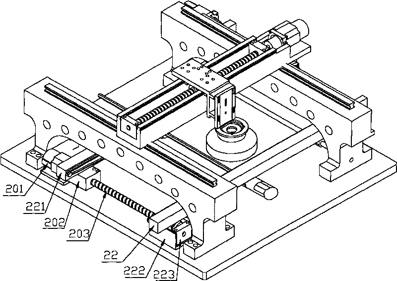
[0015] Such as figure 1 , figure 2 and Figure 4 The transmission and adjustment loading platform of an online detection equipment includes a fixed loading platform 22 and a mobile loading platform 221. One end of the mobile loading platform 221 is connected to the adjustment moving block 202 and the other end is vertically slidingly connected to the support rod 211. The adjustment The moving block 202 is threadedly connected to the adjusting screw rod 203, one end of the adjusting screw rod 203 is connected to the adjusting motor 201 and the other end is connected to the bearing of the fixed block, and one end of the fixed loading platform 22 is fixed on the U-shaped groove 222. One end of the U-shaped groove 222 is fixedly installed with a fixed block 223, and the adjusting screw 203 passes through the mouth of the U-shaped groove 222 and is connected with the bearing of the fixed block 223. A screw bearing 291 is arranged under the middle part of the table 221. The trans...


PUM


Abstract

The invention relates to an automatic optical detection device, in particular to a drive adjusting and loading platform of an online detection device, which comprises a fixing loading platform and a movable loading platform. One end of the movable loading platform is connected with an adjusting movable block and the other end thereof is vertically connected with a support rod in a sliding way, the adjusting movable block is connected with an adjusting screw rod through a screw thread, one end of the screw rod is connected with an adjusting motor and the other end thereof is connected with a fixed block bearing, a driving motor is arranged under the middle part of the fixing loading platform and is connected with a hexagonal threaded rod, the surface of the hexagonal threaded rod is contacted with the inner side of a driving belt, a rolling shaft is respectively arranged on two ends of the side of the fixing loading platform, and the side of the fixing loading platform is opposite to the adjusting loading platform. With the special design of the adjusting device, the distance between two loading platforms can be adjusted according to the size of the product to be detected, and the products with various sizes and models can be successfully and quickly detected. Moreover, the invention can be operated along with the production line synchronously, and no special personnel are needed for operation, thereby saving the human resource.

Description

technical field [0001] The invention relates to an automatic optical detection device, in particular to an on-line detection device transmission adjustment loading platform. Background technique [0002] In the prior art, when detecting defects on PCB boards (printed circuit boards), it is necessary to remove finished or semi-finished PCB boards from the PCB board production line, and test them one by one on the testing equipment. This method is usually called offline. Operation, it is usually impossible to test every product with the offline detection operation method, but adopts the method of random inspection, which not only cannot fully and effectively control the product quality, but also the random inspection is cumbersome, and needs to be tested at each Arranging special personnel responsible for testing at the entrance of the production line will greatly reduce the automation and efficiency of the entire production process. The most important thing is the quality con...

Claims


Application Information

Patent Timeline
Patent Type & Authority Applications(China)
IPC IPC(8): G01N21/956G01N21/01
Inventor 严仕新
Owner 苏州德天光学技术有限公司
Learn More