
Novel beam-balanced pumping unit

A technology of pumping units and beams, which is applied in the field of new beam balanced pumping units, can solve problems such as unsafe, easy to hit people with balancers, inconvenient management of balance blocks, etc., and achieve the goal of eliminating potential safety hazards and reducing energy consumption Effect

Inactive Publication Date: 2010-06-30
钟新 +2
View PDF0 Cites 5 Cited by
  • Summary
  • Abstract
  • Description
  • Claims
  • Application Information

AI Technical Summary

Problems solved by technology

The method of adjusting the balance torque of the crank-balanced beam pumping unit is to rely on moving the balance weight added to the crank, while the method of adjusting the balance torque of the beam-balanced pumping unit is to manually add or subtract to the balancer at the end of the beam. To adjust the balance weight, in order to make it easier for people to adjust the balance weight on the balancer, the balancer must be close to the ground. As a result, the balancer is easy to hurt people when the pumping unit is running, which is very unsafe, and the redundant balance weight is not easy to manage Therefore, it is urgent to design a new type of beam balanced pumping unit that can easily and conveniently adjust the balance moment of the pumping unit without adding or subtracting the balance weight to the balancer.

Method used


Image

  • Novel beam-balanced pumping unit
  • Novel beam-balanced pumping unit
  • Novel beam-balanced pumping unit

Examples


Embodiment Construction

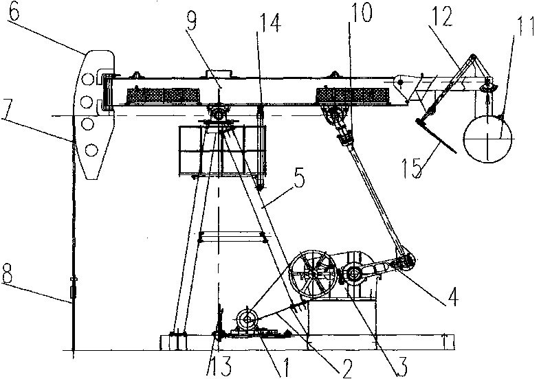
[0008] Further describe the embodiment of the present invention according to accompanying drawing below, refer to figure 1 , the new beam balanced pumping unit consists of motor (1), belt drive (2), reducer (3), crank (4), bracket (5), donkey head (6), sling (7), oil pump Rod (8), beam (9), connecting rod (10), balance weight (11), stretch rod (12), brake (13). Support rod (14) and handle (15), wherein the beam (9) Installed on the top of the bracket (5) and hingedly connected with the bracket (5), the donkey head (6) of the suspension rope (7) for hanging the sucker rod (8) is installed at the front end of the beam (9), and the rear One end of the stretch rod (12) is hinged with the balance weight (11), the other end is hinged with the beam (9), and a two-end screw thread is made in the middle of the stretch rod (12). Screw rods that rotate in the opposite direction are provided with a handle (15) at the protruding end of the lower part of the screw rod (12). Using the hand...


PUM


Abstract

The invention relates to a novel beam-balanced pumping unit which mainly consists of a motor (1), a conveying belt (2), a speed reducer (3), a crank (4), a bracket (5), a horse head (6), a lifting rope (7), a pumping rod (8), a walking beam (9), a connecting rod (10), a balancing weight (11), an extension rod (12), a brake (13), a support rod (14) and a handle (15), wherein the front end of the walking beam (9) is provided with the horse head (6), and the rear end thereof is articulated with the balancing weight (11); one end of the extension rod (12) is articulated with the walking beam, and the other end thereof is articulated with the balancing weight; the middle part of the extension rod (12) is provided with a screw rod with opposite rotating directions at the two ends; and the extending end at the lower part of the screw rod is provided with a handle (15) which is used for driving the screw rod in the middle part of the extension rod (12), the extension rod (12) can be elongated or contracted, and the balancing weight (11) swings forward or backward, so that the adjusting work of trimming moment can be completed. The novel beam-balanced pumping unit omits a small balancing weight which is inconvenient for management, adopts the walking beam for balancing so as to be convenient for management, and has good balancing effect and low energy consumption.

Description

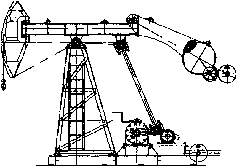
1. Technical field [0001] The novel beam-balanced pumping unit related to the invention belongs to ground equipment used for mechanical oil extraction in the petroleum industry. 2. Background technology [0002] The pumping unit is one of the main equipment for pumping crude oil in the petroleum industry. At present, more than 80% of the ground mechanical oil extraction equipment commonly used in the world uses the crank-balanced beam pumping unit. In recent years, major oil fields have gradually replaced the crank The balanced beam pumping unit is transformed into a beam-balanced pumping unit ( image 3 ). Industrial practice proves that the beam pumping unit with balanced crank can save electricity by 20-25% on average compared with the crank balanced beam pumping unit. The method of adjusting the balance torque of the crank-balanced beam pumping unit is to rely on moving the balance weight added to the crank, while the method of adjusting the balance torque of the beam-b...

Claims


Application Information

Patent Timeline
IPC IPC(8): E21B43/00
Inventor 丁友林钟有学
Owner 钟新
Learn More