Optical fiber structure and a method of producing thereof

A technology of optical waveguide and optical amplification, which is applied in the direction of manufacturing tools, clad optical fibers, glass manufacturing equipment, etc., can solve the problem of low numerical aperture, achieve consistent quality, eliminate radial and axial changes, and reduce the number of effects

Inactive Publication Date: 2010-06-23
XUNLIGHT CORPORATION
View PDF2 Cites 0 Cited by
  • Summary
  • Abstract
  • Description
  • Claims
  • Application Information

AI Technical Summary

Problems solved by technology

In some cases the numerical aperture may be accidentally too low

Method used


Image

  • Optical fiber structure and a method of producing thereof
  • Optical fiber structure and a method of producing thereof
  • Optical fiber structure and a method of producing thereof

Examples


Embodiment Construction

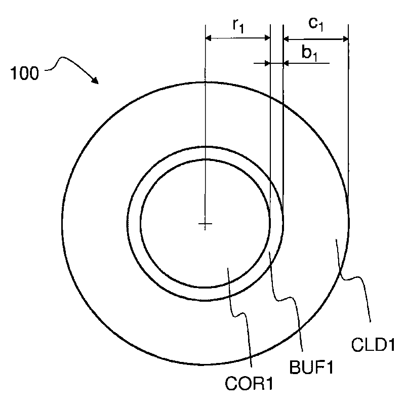
[0071] refer to Figure 1a , the optical amplifying buffered optical fiber 100 includes a core COR1, a buffer BUF1, and a cladding CLD1. The buffer layer BUF1 has a ring shape, and it surrounds the core COR1. The cladding layer CLD1 also has a ring shape and it surrounds the buffer layer BUF1. The core COR1 has a radius r 1 . The buffer layer has a radial dimension b 1 . The cladding has a radial dimension c 1 .

[0072] The buffered fiber 100 may be a large mode area (LMA) fiber such that the effective mode area is greater than or equal to 200 μm 2 . The buffered fiber 100 can be sized as a single mode fiber, or only support 2-4 transverse modes.

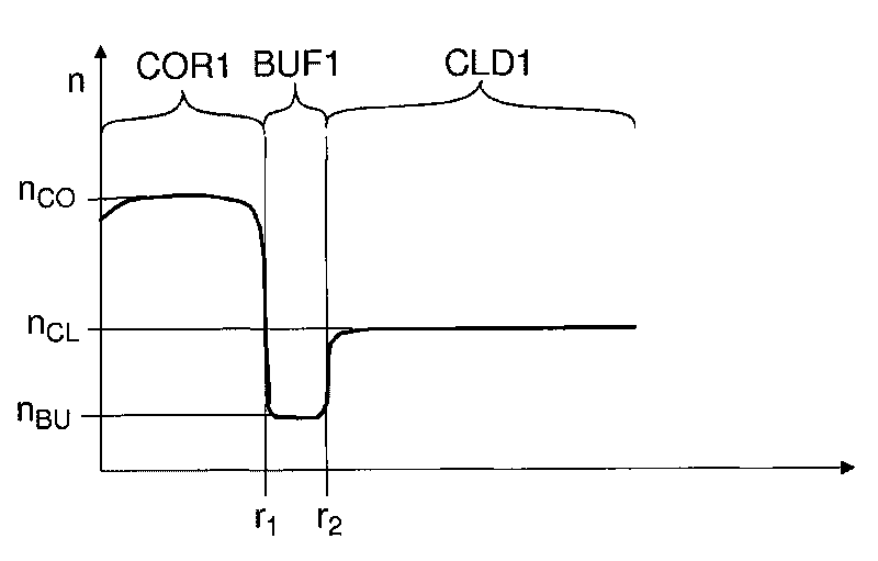
[0073] refer to Figure 1b , the refractive index n of the core COR1 CO than the refractive index n of the cladding layer CLD1 CL large in order to confine the waveguided light in the core COR1.

[0074] The refractive index n of the cladding layer CLD1 can be selected CL to achieve the desired numerical aperture NA of...


PUM

PropertyMeasurementUnit
sizeaaaaaaaaaa
sizeaaaaaaaaaa
sizeaaaaaaaaaa

Abstract

An optical waveguide (100) comprises a core (COR1), a buffer (BUF1) surrounding said core (COR1), and a cladding (CLD1) surrounding said buffer (BUF1), said core (COR1), said buffer (BUF1) and said cladding (CLD1) comprising silica glass, and the refractive index (nBU) of said buffer (BUF1) being substantially equal to the refractive index of pure amorphous silica glass. The buffer (BUF1) may reduce bubble formation during manufacturing and may facilitate splicing of the waveguide (100). The numerical aperture of the waveguide (100) may be fine-tuned by adjusting the radial dimension (b1) of the buffer (BUF1) in order to compensate variations in the refractive index (nCO) of the core (COR1).

Description

technical field [0001] The present invention relates to optical fibers, and methods of making the same. Background technique [0002] Optical systems based on large mode area (LMA) fibers, amplifiers, or lasers may require good beam quality. The beam quality provided by optically amplifying fibers can be improved by choosing a low numerical aperture (NA), but said low numerical aperture does not support the transmission of higher order modes. [0003] It is well known that the numerical aperture of an optical fiber can be reduced by increasing the refractive index of the cladding. [0004] Fabrication of large mode area fibers requires tight control of numerical aperture. Manufacturing processes (eg, core deposition) do not always allow precise control of the refractive index, and there can be variation in the numerical aperture of the resulting fiber. Therefore, there may be undue variation in the numerical aperture of the fabricated fiber. In some cases, the numerical ...

Claims


Application Information

Patent Timeline
Patent Type & Authority Applications(China)
IPC IPC(8): G02B6/036C03B37/01C03C13/04C03B37/012
CPCG02B6/03627G02B6/02019C03B2207/34C03B37/0142C03B2201/31C03B2207/06C03B37/01211C03B2201/36C03B2207/14C03B2201/34Y02P40/57
Inventor M·拉贾拉M·霍托利努P·斯特尼厄斯H·瓦尔科南S·塔梅拉P·基维里
Owner XUNLIGHT CORPORATION
Why Eureka
Try Eureka