
Single-stage high-power-factor feedback frequency conversion type resonant energy control circuit

A control circuit, high power factor technology, applied in the direction of high-efficiency power electronic conversion, AC power input conversion to AC power output, electrical components, etc. Improve and improve the effect of lamp luminous efficiency

Inactive Publication Date: 2010-06-23
江桂香 +3
View PDF0 Cites 5 Cited by
  • Summary
  • Abstract
  • Description
  • Claims
  • Application Information

AI Technical Summary

Problems solved by technology

[0006] 3. The above two items need to be connected with a field effect transistor (MOSFET) drive IC, which is costly
[0007] 4. At present, in terms of lamp lighting on the market, the preheating start needs to heat the electrode to start the lamp. After starting, continue to heat the electrode to run, which will cause losses
[0009] (1) Frequency modulation control: By controlling the switching frequency and changing the lamp current to achieve the purpose of dimming, if this method adjusts different wattages, the resonant circuit will be in a non-resonant state, so the conversion efficiency will be reduced and the luminous efficiency will be reduced.
[0010] (2) Amplitude modulation control: This circuit adjusts the level of the input voltage at a fixed resonant frequency. This method cannot be started when the illumination is low
[0011] (3) Phase modulation control: This circuit operates the power supply frequency and adjusts it to achieve the effect of dimming. This method requires 4 full-bridge switches, which is expensive

Method used


Image

  • Single-stage high-power-factor feedback frequency conversion type resonant energy control circuit
  • Single-stage high-power-factor feedback frequency conversion type resonant energy control circuit
  • Single-stage high-power-factor feedback frequency conversion type resonant energy control circuit

Examples


Embodiment Construction

[0035] In order to fully understand the technical content of the present invention, the technical solutions of the present invention will be further introduced and explained below in accordance with the drawings and in combination with the embodiments of the present invention.

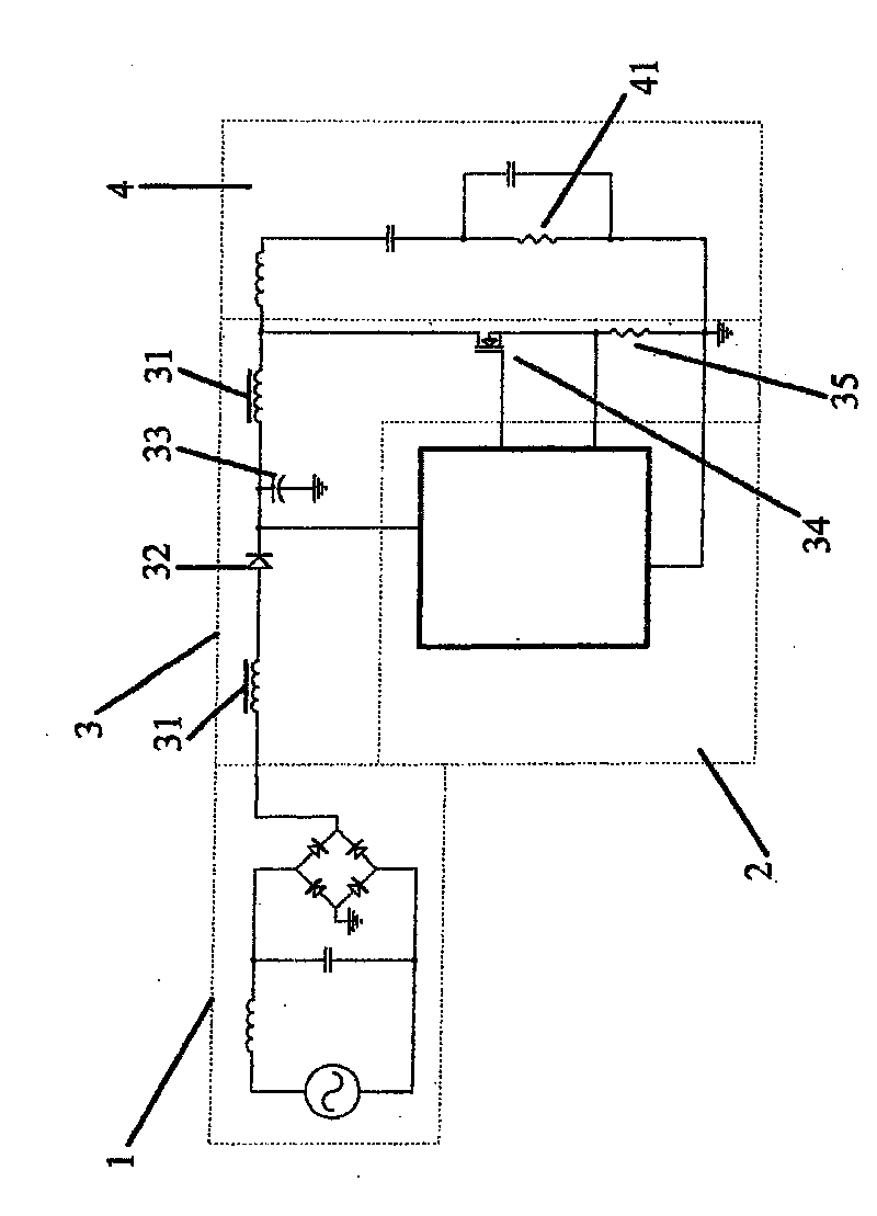
[0036] see figure 1 As shown, the present invention is a control circuit for single-stage high power factor feedback variable frequency resonant energy, the circuit includes a set of power filter circuit 1, a set of electronic circuit combination circuit 2, a set of high power factor pulse width control Loop 3, a set of resonant networks 4.

[0037] Utilize the electronic circuit combination circuit 2 to directly drive a field effect transistor (MOSFET) 34, when the field effect transistor (MOSFET) 34 is turned on, the energy is stored on the transformer 31, and the resonance energy of the resonant network 4 is released simultaneously; when the field effect transistor (MOSFET) ) 34OFF, the transformer...


PUM


Abstract

The invention relates to a single-stage high-power-factor feedback frequency conversion type resonant energy control circuit which comprises a set of power filter circuits, a set of electronic circuit combination loops, a set of high-power-factor pulse width control loops and a set of resonant networks, wherein each high-power-factor pulse width control loop internally comprises a transformer, two winding coils and a metal-oxide-semiconductor field effect transistor (MOSFET); and high-power-factor fixing power with settable feedback can be reached through the electronic circuit combination loops and resonant loops. The technology can be used for tube dimming and also ensure that the light emitting efficiency of tubes is improved, is suitable for tunes of various types of energy-saving lamps, daylight lamps, LED lamps, HID lamps, and the like, and can reduce the cost.

Description

technical field [0001] Based on the design principle of general high-frequency power supply, the present invention integrates the high-power factor circuit and the half-bridge resonant circuit into two sets of coils wound by a transformer, and a field-effect transistor (MOSFET), to achieve the maximum resonance energy. Distribution, so that it has high power factor, adjustable fixed feedback resonance energy, so it can replace the circuit of the previous technology. Background technique [0002] 1. The current control chip on the market requires an additional driver chip, which contains an AD converter, which is costly. To improve the power factor, it also needs to add an IC to improve the power factor. [0003] 2. Currently, there are ways to improve publicity in the market: [0004] (1) It is necessary to use an inductor, a capacitor, and a field effect transistor (MOSFET) to control and integrate the AC power supply so that the voltage and current of the mains are synchr...

Claims


Application Information

Patent Timeline
IPC IPC(8): H02M5/458H02M1/42
CPCY02B70/126Y02B70/10
Inventor 江桂香黄国洪黄翊黄千硕
Owner 江桂香
Learn More