
Well blowout preventer mounted in drilling column and automatically controlled in well

A blowout preventer and drill string technology, which is applied in wellbore/well components, earthwork drilling, sealing/packing, etc. Comprehensive technical and economic benefits, saving operating costs, and reliable work

Inactive Publication Date: 2010-06-23
SOUTHWEST PETROLEUM UNIV
View PDF0 Cites 16 Cited by
  • Summary
  • Abstract
  • Description
  • Claims
  • Application Information

AI Technical Summary

Problems solved by technology

Serious accidents will occur if the operator is inexperienced or negligent at work and fails to detect signs of well kick or blowout in time
However, the downhole safety valve in use can only complete the blowout prevention in the drill string and cannot realize the blowout prevention of the whole well. Therefore, it is difficult to realize all the operations of downhole blowout prevention when abnormal conditions occur downhole.
In addition, because it takes a certain amount of time for the information of abnormal phenomena in the downhole to be transmitted to the wellhead through the medium, the downhole annulus may already have a local lack of mud due to a well kick at this time, which increases the pressure difference in the downhole annulus and intensifies the control of blowout. difficulty

Method used


Image

  • Well blowout preventer mounted in drilling column and automatically controlled in well
  • Well blowout preventer mounted in drilling column and automatically controlled in well
  • Well blowout preventer mounted in drilling column and automatically controlled in well

Examples


Embodiment Construction

[0013] The present invention will be further described below in conjunction with drawings and embodiments.

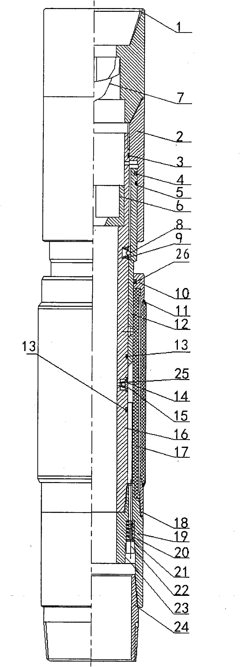
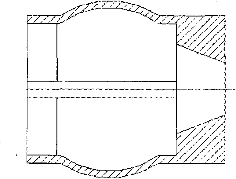
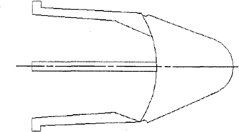
[0014] The downhole blowout preventer is composed of the drilling tool slide valve assembly and the main body of the downhole blowout preventer, such as figure 1 shown. Among them, the drilling tool spool valve assembly is composed of spool valve joint 1, spool valve seat 6, and spool valve body 7. Two-stage shaft shoulders are processed on the spool valve joint 1, and one is used for positioning and restricting the spool valve body 7. 7 downstrokes. One is used to install the spool valve seat 6 during the initial connection. The upper circular ring of the spool valve seat 6 is processed with a tapered hole, and a certain number of elastic elements are installed around it to facilitate close contact with the inner wall of the drill string, such as figure 2 shown. The upper part of the spool valve body 7 is a conical cylinder composed of multiple arcs and straight li...


PUM


Abstract

The invention relates to a well blowout preventer mounted in a drilling column and automatically controlled in a well, which is capable of automatically closing the well during the well kick or the well blowout of oil-gas fields in the process of drilling the well. The invention is capable of automatically controlling the well blowout and also unlocking the blowout preventer in time so as to ensure the continuousness, safety and reliability in the process of drilling the well. The technical scheme is: a drilling tool slide valve assembly comprises a slide valve joint, a slide valve body and a slide valve seat, one end is connected to the drilling column and the other end is connected with a well blowout preventer main body. One end of the collar of the well blowout preventer main body is connected with the slide valve joint and a central tube, the collar thereon is provided with two stepped annular grooves, a clamp spring is mounted on a piston and in contact with the inner wall of the collar, a clamp pin and a clamp pin spring are mounted in the flute of the central tube, a slip ring sealing ring is mounted in the flute of the inner wall of a slip ring, a protrusion-preventing ring is mounted at the junction of a rubber barrel and the slip ring, one end of a support ring is connected with the valve body, the other end thereof is connected with the rubber barrel and the protrusion-preventing ring to form a blowout-preventing sealing device. The invention has simple structure, reliably works, is capable of effectively preventing the well blowout, and improves technical benefit and economical benefit.

Description

technical field [0001] The invention relates to a downhole blowout preventer installed in the drill string and automatically controlled downhole, which can automatically complete the shut-in operation inside and outside the drill string when well kick or blowout occurs in the well drilling process of oil and gas fields. Background technique [0002] At present, the blowout preventers used in the drilling process of oil and gas fields are mostly installed at the wellhead. When the operator finds a severe blowout phenomenon downhole on the well, the control system is turned on to complete the wellhead blowout preventer shut-in operation to prevent blowout accidents. The action of this type of blowout preventer must rely on the experience and sense of responsibility of the operator to prevent blowout accidents. If the operator's inexperience or negligence during work fails to detect well kick or blowout signs in time, serious accidents will occur. The downhole safety valve in ...

Claims


Application Information

Patent Timeline
IPC IPC(8): E21B33/06
Inventor 杨启明刘清友杨旭文
Owner SOUTHWEST PETROLEUM UNIV
Learn More