Imaging method and imaging device in three-function mode in ultrasonic system
An ultrasound system and imaging method technology, applied in optics, instruments, photography, etc., can solve the problems of poor imaging quality, no matching degree, image misalignment, etc., to shorten the time interval, improve the time matching degree, and avoid the phenomenon of misalignment. Effect
- Summary
- Abstract
- Description
- Claims
- Application Information
AI Technical Summary
Problems solved by technology
Method used
Image

Examples
Embodiment 1
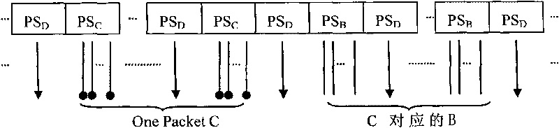
[0025] Embodiment 1: On the basis of the above technical solution, after completing the C-line scan insertion of a data packet, insert the B-line scan. This can more effectively shorten the interval time between images obtained by each type of pulse scanning. For details, please refer to image 3 and Figure 4 instruction of. Inserting the B-line scan after completing the C-line scan insertion of a data packet is the optimal implementation mode of the present invention.
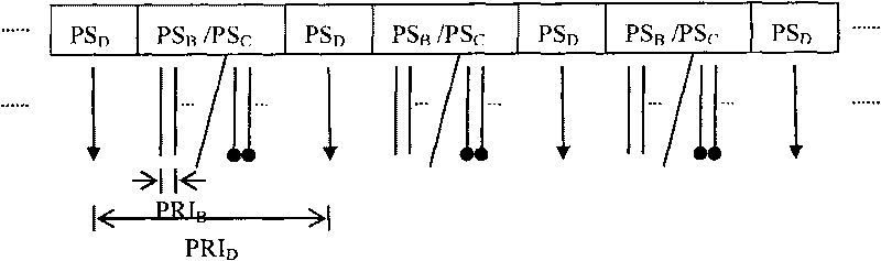
[0026] In this embodiment, since there is a cross scan when the C pulse is emitted, if the number of cross scans is denoted as K, the number of repeated transmissions of the same scan line is denoted as P, and the C pulse emitted during the nth scan of the mth scan line is denoted by C m,n Represent, wherein m=1, 2, ... K; n = 1, 2, ... P; then the sequence of transmitting C pulses in a Packet (data packet) is:
[0027] C 1,1 , C 2,1 ...C K,1 , C 1,2 , C 2,2 ...C K,2 ,...,C 1,P , C 2,P ...C K,P ...
Embodiment 2
[0029] Example 2: see image 3 , on the basis of Embodiment 1, the time interval of the above-mentioned D-line scanning includes: several first time intervals, which are equal to the interval PRI between two adjacent emission D pulses D . image 3 The C / B pulse emission scan sequence is given. in several PRIs D Insert a Packet (data packet) C-line scan in the interval, and then immediately, in several PRI DThe B-line scan corresponding to the above-mentioned one Packet (data packet) C-line scan is inserted in the interval. Since Color imaging is a C-line scan, there is a cross-scan, and the ultrasound system calculates the number K of cross-scans according to the parameters selected by the user, and K is the number of C-line scans inserted in the first time interval.
[0030] Based on the sampling line selected by the user, the D-line emission scan corresponding to the sampling line is determined. for example image 3 , the ultrasound system uses PRI for the sampling lin...
Embodiment 3
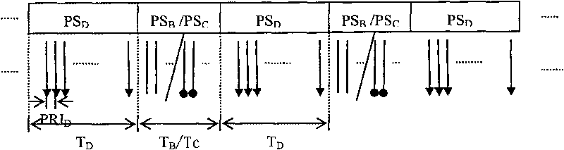
[0032] Embodiment 3: see Figure 4 , on the basis of Embodiment 1, the time interval of the above-mentioned D-line scan data includes: a second time interval, which is equal to the scanning interval of two adjacent continuous emission D pulses, assuming that the time of continuous emission D pulse is T D , then two adjacent T D is the second time interval. Figure 4 The C / B pulse emission scan sequence is given. The ultrasound system determines the continuous emission scan time T of the B line according to the parameters selected by the user B , the continuous emission scan time T of line C C , the continuous emission scan time T of line D D . Among them, T C It is the time to scan a Packet C line. The ultrasound system determines T from user-selected parameters B The number of inserted B lines.
[0033] Because there are cross-scans in Color imaging, the ultrasound system calculates the number K of cross-scans according to the parameters selected by the user. The em...
PUM
 Abstract
Description
Claims
Application Information
 - R&D
- Intellectual Property
- Life Sciences
- Materials
- Tech Scout
- Unparalleled Data Quality
- Higher Quality Content
- 60% Fewer Hallucinations
Browse by: Latest US Patents, China's latest patents, Technical Efficacy Thesaurus, Application Domain, Technology Topic, Popular Technical Reports.
© 2025 PatSnap. All rights reserved.Legal|Privacy policy|Modern Slavery Act Transparency Statement|Sitemap|About US| Contact US: help@patsnap.com