
Uplink power control method, system and equipment

A technology for user equipment and transmit power, which is applied in the control/equalization of transmission, communication between multiple stations, etc. It can solve the problems of large path loss, inaccurate assumptions, affecting the accuracy of resource scheduling, etc. Interfere and improve system performance

Inactive Publication Date: 2010-06-16
CHINA MOBILE COMM GRP CO LTD
View PDF0 Cites 60 Cited by
  • Summary
  • Abstract
  • Description
  • Claims
  • Application Information

AI Technical Summary

Problems solved by technology

[0019] In the existing uplink power control scheme, the parameters to be adjusted include P O_nominal_PUSCH (j), P O_UE_PUSCH (j), α and Ks, many parameters lead to complex operations, and it is difficult to jointly adjust multiple parameters to achieve a reasonable value during uplink power control, making it difficult to achieve better system performance;
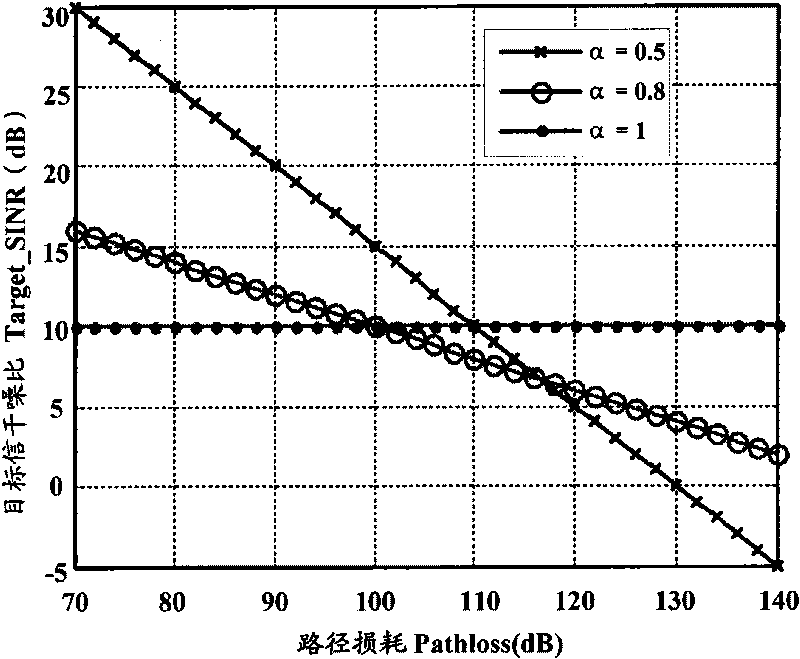
[0020] According to the existing uplink power control scheme, the relationship between Pathloss and Target_SINR (Target Signal to Interference Noise Ratio) of the UE in the serving cell is obtained as follows figure 1 As shown, there is a simple linear relationship, that is to say, the existing uplink power control scheme assumes that the inter-cell interference generated by the UE with a large path loss in the serving cell is also large, but this assumption is inaccurate, because the UE in the serving cell The path loss in the serving cell and the inter-cell interference generated by it are not a simple linear relationship;
[0021] Although the existing uplink power control scheme introduces a parameter α that affects inter-cell interference, the parameter α is a semi-static configuration and takes the same value in the entire cell, which makes the consideration of inter-cell interference relatively simple and rough, and it is difficult to The inter-cell interference generated by the UE is controlled within the target range. When the inter-cell interference changes greatly, the existing uplink power control scheme cannot suppress the inter-cell interference generated by the UE in a timely and accurate manner, which affects the accuracy of resource scheduling and further affects the system performance

Method used


Image

  • Uplink power control method, system and equipment
  • Uplink power control method, system and equipment
  • Uplink power control method, system and equipment

Examples


Embodiment Construction

[0040] Aiming at the disadvantages of the uplink power control scheme proposed in the existing 3GPP LTE Release 8, the embodiment of the present invention proposes an improved uplink power control scheme, which introduces the path loss from the UE to the adjacent non-serving cell, and uses Pathloss j (1≤j≤M) indicates that M is the number of adjacent non-serving cells, and j is the number of adjacent non-serving cells. It should be noted that the path loss Pathloss from the UE to the adjacent non-serving cell introduced in the embodiment of the present invention j(1≤j≤M) does not introduce additional system overhead. In the prior art, in order to perform inter-cell handover, the UE needs to measure the reference signal received power of the adjacent cell. In the embodiment of the present invention, the measurement result of the reference signal received power of the adjacent cell by the UE is effectively used. All the measured adjacent cells can be regarded as adjacent non-se...


PUM


Abstract

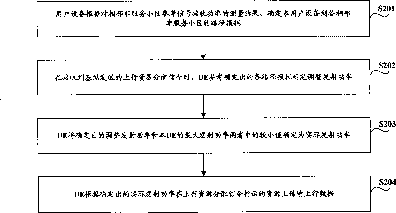
The invention discloses an uplink power control method, a system and equipment, which is used for accurately inhibiting intercell interference of user equipment timely and improving system performance. The uplink power control method comprises: user equipment determines the path loss of the user equipment to each adjacent non-service cell according to the measuring result of the reference signal received power of the adjacent non-service cell by the user equipment; when receiving an uplink resource assignment signalling transmitted by a base station, the user equipment determines adjusted transmission power by referring to the each determined path loss, and determines a minor value between the determined adjusted transmission power and the maximum transmission power of the user equipment to be the practical transmission power; according to the determined practical transmission power, uplink data is transmitted on resource indicated by the uplink resource assignment signalling.

Description

technical field [0001] The invention relates to the technical field of mobile communication, in particular to an uplink power control technology. Background technique [0002] 3GPP (3rd Generation Partnership Project, the third generation mobile communication standardization organization) has started the standardization work of LTE (Long Term Evolution, long-term evolution), and the LTE system is based on OFDM (Orthogonal Frequency Division Multiplex, Orthogonal Frequency Division Multiplexing) technology. In order to support multi-user sharing of channel resources, a dynamic scheduling method is used to allocate data transmission resources for UE in real time, and eNB (Evolved Node-B, evolved base station) allocates uplink data transmission resources for UE through UL Grant (uplink resource allocation signaling) resources, the UE transmits UL Data (uplink data) on the resources indicated by the UL Grant. [0003] 3GPP LTE Release 8 (Version 8) specifies that the adopted up...

Claims


Application Information

Patent Timeline
Patent Type & Authority Applications(China)
IPC IPC(8): H04B7/005H04B7/26
Inventor 姜大洁龙紫薇
Owner CHINA MOBILE COMM GRP CO LTD
Learn More