
Method for modulating waveform of gate driving signal and architecture thereof

A gate drive and signal modulation technology, applied in the field of gate drive signal generation, can solve the problems of scanning waveform deformation, uneven image color, complex circuit and so on

Inactive Publication Date: 2010-06-16
INNOLUX CORP
View PDF0 Cites 4 Cited by
  • Summary
  • Abstract
  • Description
  • Claims
  • Application Information

AI Technical Summary

Problems solved by technology

In addition to the slightly complicated circuit, the adjustment of the driving waveform must take into account the above two control signals and the resistance value of the discharge chamfer, and the resistor for chamfering will consume power all the time, and the thin film transistor is driven by a square wave with chamfering The gate also has a disadvantage, that is, when the scanning line is very long, the scanning waveform at the end will be seriously deformed, resulting in uneven color of the image under the same gray scale

Method used


Image

  • Method for modulating waveform of gate driving signal and architecture thereof
  • Method for modulating waveform of gate driving signal and architecture thereof
  • Method for modulating waveform of gate driving signal and architecture thereof

Examples


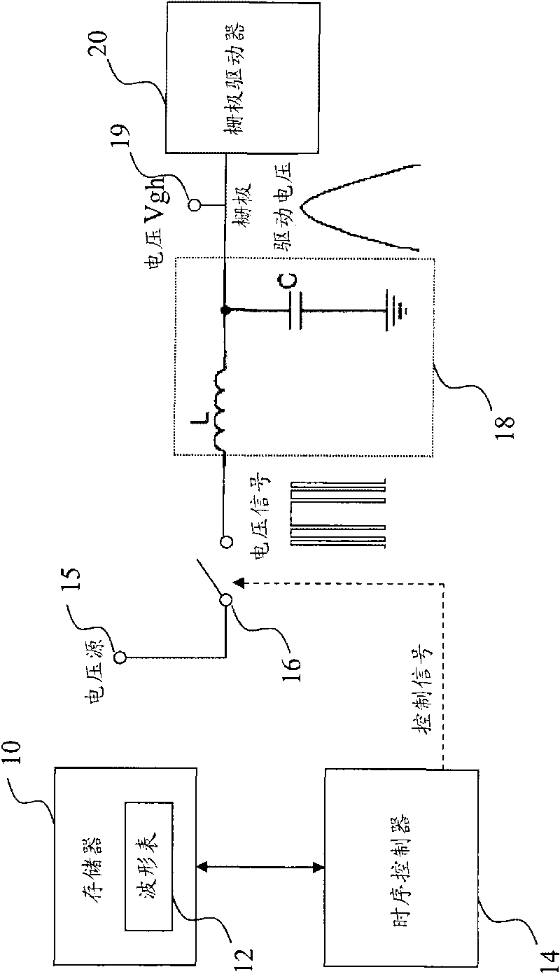
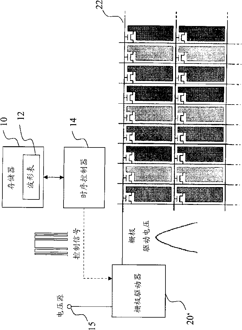
Embodiment Construction

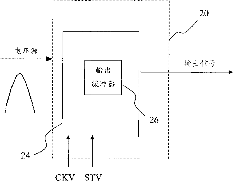
[0027] The present invention provides a method for modulating a waveform of a gate driving signal and its structure. Taking a sinusoidal waveform driving signal as an example, two methods are used to modulate the voltage waveform sent by a gate driver to a scanning line.

[0028] figure 1 It is the first implementation framework of the modulation waveform of the gate drive signal in the present invention, including a memory 10, a timing controller 14, a switch 16, a low-pass filter 18 and a gate driver 20, and the memory 10 is electronically erased Electrically Erasable Programmable Read-Only Memory (EEPROM), in which a waveform table 12 is stored, and the waveform table 12 is used to record the relevant settings of the gate driving signal, including the waveform sent by the gate driver 20 to the scanning line Size and width, for example, program codes of 0 and 1 are stored, representing low and high waveforms respectively; the timing controller 14 reads the waveform table 12 ...


PUM


Abstract

The invention discloses a method for modulating a waveform of a gate driving signal and an architecture thereof. The method for modulating the waveform of the gate driving signal comprises the steps that: firstly, a waveform table is set and stored in a storage, wherein the waveform table has the sizes and widths of the scanning line waveforms; a time schedule controller reads the waveform table from the storage, outputs a control signal to drive a switch to open and close according to a value of the waveform table; simultaneously, a voltage source outputs a high voltage, coverts the control signal into a gate driving voltage and transmits the gate driving voltage to a gate driver; a high frequency part of the gate driving voltage is filtered through a low pass filter so as to obtain a preset waveform in the waveform table; and the high frequency part of the gate driving voltage also can be filtered in the gate driver, and then the gate driving voltage is amplified and output to each scanning line one by one; or the gate driving voltage is filtered by the scanning lines per se.

Description

technical field [0001] The invention relates to a new gate drive signal generation technology in a thin-film transistor liquid crystal display (TFT LCD), in particular to a method for modulating a waveform by a gate drive signal and its structure. Background technique [0002] Press, at present, the gate signal for driving a thin film transistor liquid crystal display (TFT LCD) is roughly composed of two parts, one of which is a timing controller that generates two complementary control signals, which are matched with the switching and discharging of metal oxide semiconductor field effect transistors. The resistor forms a DC voltage that converts the oscillating voltage VGHP into a cycle driving voltage Vgh with discharge decay characteristics, and the driving voltage is directly provided to the gate driving circuit of the thin film transistor liquid crystal display. At the same time, the timing controller provides a control signal to control when the gate driving circuit sh...

Claims


Application Information

Patent Timeline
Patent Type & Authority Applications(China)
IPC IPC(8): G09G3/36
Inventor 蔡怀进李俊明
Owner INNOLUX CORP
Learn More