
Falling-off test device and usage thereof

A testing device and technology to be tested, applied in measurement devices, impact testing, testing of machine/structural components, etc., can solve problems such as inconvenience, collision phenomenon, material cost burden, etc., and achieve the effect of reducing cost and improving repeatability

Inactive Publication Date: 2011-11-16
POWERTECH TECHNOLOGY
View PDF0 Cites 0 Cited by
  • Summary
  • Abstract
  • Description
  • Claims
  • Application Information

AI Technical Summary

Problems solved by technology

[0004] 1. The repeatability of the test is low
It is difficult to manually locate the height and angle of the object to be tested, so the angle of each drop and the area of ​​impact may be different, so each test may get completely different results
[0005] 2. The cost of the experiment is high, and the preparation time is time-consuming: Due to the low repeatability of the experiment, many test items may need to be prepared, and after each design change, the test items must be prepared again, especially in the product development stage. The cost unit price is high, and the drop test is a destructive test, so repeated testing will be a material cost burden
[0006] 3. Collisions may occur during the drop test, and non-linear phenomena may occur when the object to be tested is dropped
[0007] 4. The existing known drop test device can only apply the standard specified by a single test condition, and its test parameters are fixed values, such as the shock wave (impulse) generated during the test impact at a fixed height H
When the package type of the object to be tested is different or the application environment is different, the test conditions cannot be changed, especially the drop test standards used by each manufacturer are different, so each time a test condition is changed, it is necessary to purchase another set of drop test device, resulting in high cost of testing
[0008] It can be seen that the above-mentioned existing drop test device and its use method obviously still have inconvenience and defects in product structure, test method and use, and need to be further improved urgently.
In order to solve the above-mentioned problems, the relevant manufacturers have tried their best to find a solution, but no suitable design has been developed for a long time, and there is no suitable structure and method for general products and methods to solve the above-mentioned problems. This is obviously a problem that relevant industry players are eager to solve

Method used


Image

  • Falling-off test device and usage thereof
  • Falling-off test device and usage thereof
  • Falling-off test device and usage thereof

Examples


Embodiment Construction

[0060] In order to further explain the technical means and effects of the present invention to achieve the intended purpose of the invention, the specific implementation, structure, The method of use, steps, features and effects thereof are described in detail below.

[0061] Embodiments of the present invention will be described in detail below in conjunction with the attached drawings, but it should be noted that these drawings are simplified schematic diagrams, and are only used to illustrate the basic structure or implementation method of the present invention, so only the same as shown The relevant components and combination of this case are that the components shown in the figure are not drawn in proportion to the number, shape, and size of the actual implementation, and some dimensional ratios and other related dimensional ratios have been exaggerated or simplified to provide better Clear description. The number, shape and size ratio of the actual implementation is an ...


PUM


Abstract

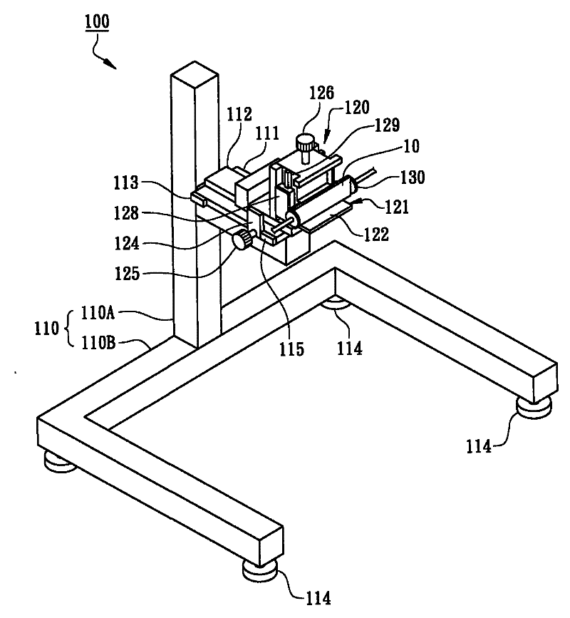
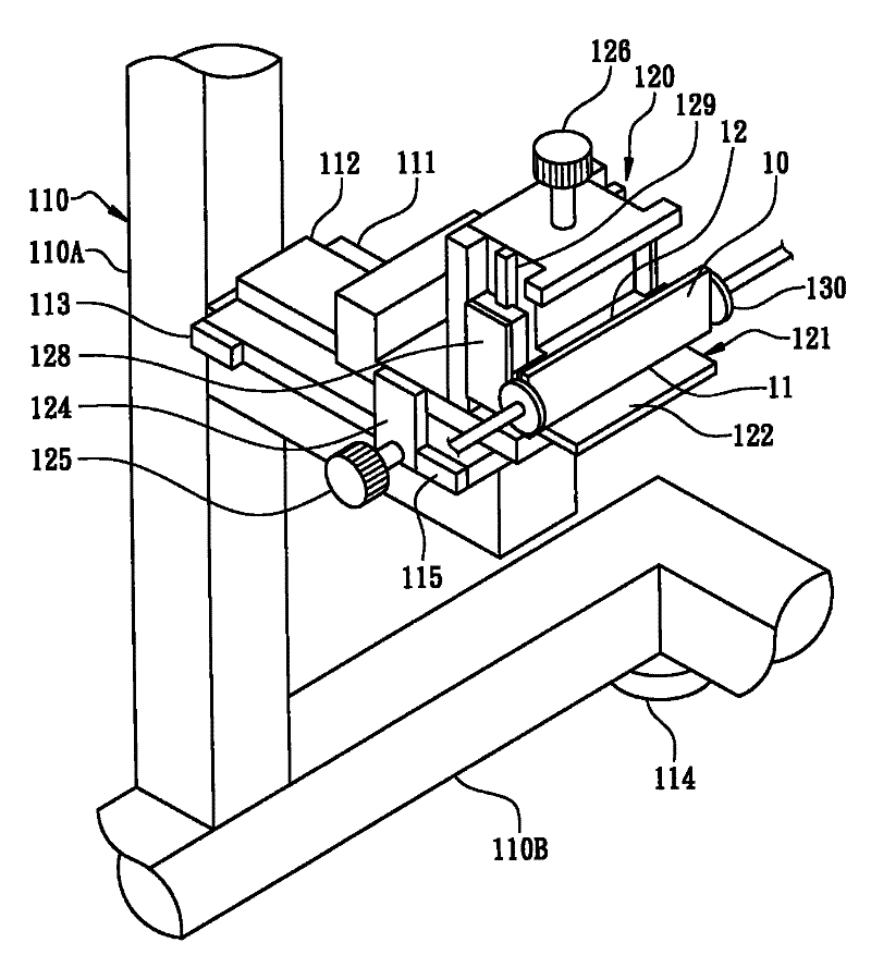
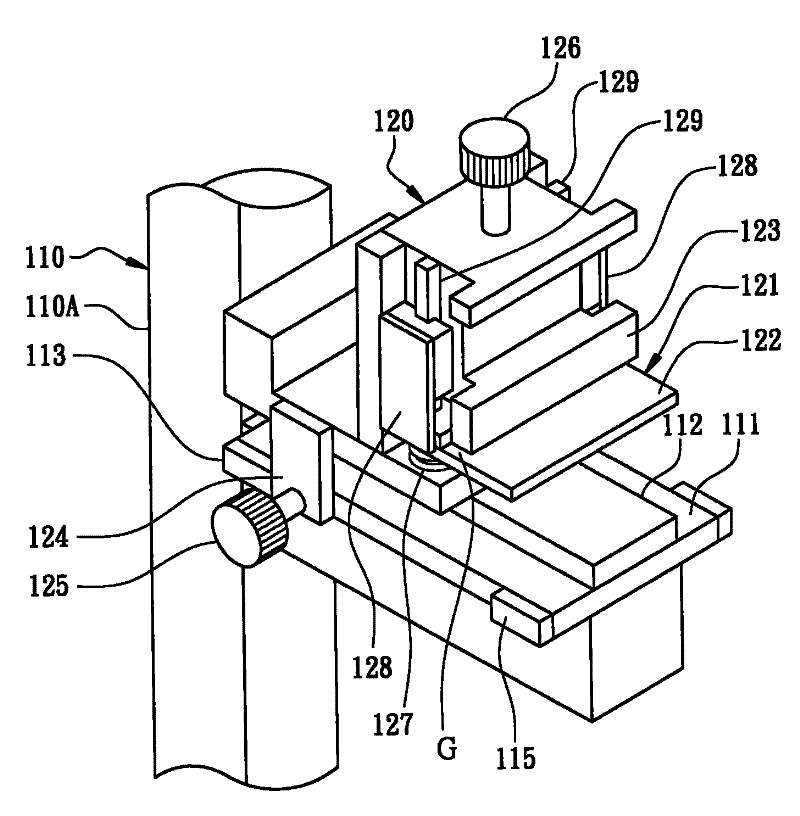
The invention relates to a falling-off test device and a usage thereof. The falling-off test device comprises a fixing frame, a falling-off angle setting jig and a holder; the fixing frame is provided with a slide carriage which is equipped with a horizontal slide rail; the falling-off angle setting jig is arranged on the slide carriage and connected with a sampling rack for regulating hoisting and descending, the sampling rack is provided with a first reference plane, the jig is provided with a second reference plane, the motion of hoisting and descending of the sampling rack causes the first reference plane to move between a first setting position and a first withdrawing position, the jig moves horizontally under guidance of the horizontal slide rail, and the second reference plane moves between a second setting position and a second withdrawing position; and the holder holds the object to be tested. The invention is applicable to testing falling-off surfaces in different angles of the objects to be tested with different sizes, and can adjust the different test conditions.

Description

technical field [0001] The invention relates to a static or dynamic balance test of a machine or a structural part, in particular to a drop test device for a semiconductor chip package product and a use method thereof. Background technique [0002] In order to ensure that the product can maintain the quality of the original design in the user's operating environment and during the transportation process, for example, after the chip package structure is packaged, the final product test is usually carried out, such as aging test, electrical test, tensile test, solder ball bonding Strength tests, etc., to ensure its quality and reliability, and then assembled into electronic products such as memory (memory is memory, referred to as memory in this article) modules (or modules), which can be modularly combined and applied to general daily necessities Common computer mainframes, mobile phones, digital cameras, PDAs, etc. have higher requirements on the characteristics of impact an...

Claims


Application Information

Patent Timeline
Patent Type & Authority Patents(China)
IPC IPC(8): G01M7/08
Inventor 苏庭锋
Owner POWERTECH TECHNOLOGY
Learn More