Filling joint

The technology of a liquid filling pipe and a mounting seat is applied in the field of filling joints, which can solve the problems of inconvenient installation, difficult adjustment, and difficult sealing, and achieve the effects of convenient installation, not easy to be corroded, and simple and reliable sealing.

Inactive Publication Date: 2010-06-16
ZHANGJIAGANG FURUI SPECIAL EQUIP CO LTD
View PDF0 Cites 0 Cited by
  • Summary
  • Abstract
  • Description
  • Claims
  • Application Information

AI Technical Summary

Problems solved by technology

[0002] At present, the traditional filling joints are all in the form of horns, which are not easy to seal. Moreover, the seals used are hard seals. The sealing surface is exposed to the outside for a long time, and dirt is easy to adhere to, corrode the sealing surface, and cause leakage; moreover, the filling joints The mounting holes are all fixed holes, not easy to adjust, and inconvenient to install

Method used


Image

  • Filling joint
  • Filling joint
  • Filling joint

Examples


Embodiment Construction

[0011] The specific embodiments of the present invention will be described in detail below with reference to the accompanying drawings.

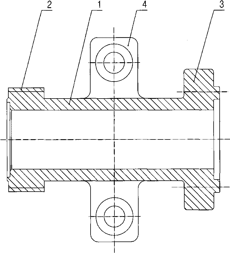
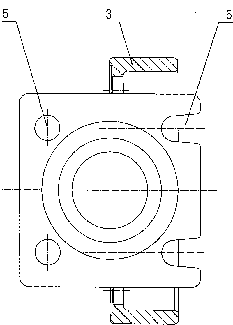
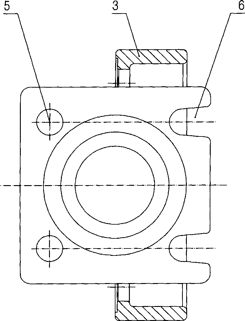
[0012] Such as figure 1 As shown, a filling joint according to the present invention includes: a filling pipe 1, two ends of the filling pipe 1 are respectively provided with a sealing thread 2 and a mounting seat 3, and a connecting body 4 is provided in the middle of the filling pipe 1 ;Such as figure 2 As shown, in this embodiment, one side of the mounting base 3 is provided with a pair of mounting holes 5, and the other side of the mounting base 3 is provided with a pair of mounting grooves 6 opening outward.


PUM


Abstract

The invention discloses a filling joint with easy sealing and a nondisclosure sealing surface. The filling joint comprises a liquid filled pipe. Sealing threads and an installation seat are respectively arranged at both ends of the liquid filled pipe, and a connecting body is arranged at the middle part of the liquid filled pipe. In the invention, a threaded sealing mode is adopted, and therefore, sealing is simple and reliable; in addition, the sealing surface is not exposed outsides, thereby enabling the sealing surface not to be easy to corrode.

Description

Technical field [0001] The invention relates to a filling joint for filling low-temperature liquefied gas such as liquid oxygen, liquid argon, and liquid nitrogen. Background technique [0002] At present, the traditional filling joints have a claw-shaped structure, which is not easy to seal. Moreover, the used seal is a hard seal, and the sealing surface is exposed to the outside for a long time. It is easy for dirt to adhere to the sealing surface and cause leakage; moreover, the filling joint The mounting holes are all fixed holes, which are not easy to adjust and inconvenient to install. Summary of the invention [0003] The technical problem to be solved by the present invention is to provide a filling joint which is very easy to seal and the sealing surface is not exposed. [0004] In order to solve the above technical problems, the technical solution adopted by the present invention is: a filling joint, comprising: a filling pipe, the two ends of the filling pipe are respect...

Claims


Application Information

Patent Timeline
IPC IPC(8): F17C5/06
Inventor 郭立新胡晨曦
Owner ZHANGJIAGANG FURUI SPECIAL EQUIP CO LTD
Why Eureka
Try Eureka