The structure and use method of wafer combination wheel of cleaning equipment after cmp

A combined wheel and post-cleaning technology, applied in the directions of cleaning methods and utensils, chemical instruments and methods, etc., can solve the problems of easy jamming of the wafer idler, affecting the accuracy of speed measurement, and large swing of the wafer idler, so as to improve the rigidity. , to ensure the rationality of the layout, the effect of reducing the swing of the idler

Active Publication Date: 2019-02-05
BEIJING SEMICORE PRECISION MICROELECTRONICS EQUIP CO LTD
View PDF6 Cites 0 Cited by
  • Summary
  • Abstract
  • Description
  • Claims
  • Application Information

AI Technical Summary

Problems solved by technology

[0003] The invention provides a wafer combination wheel structure and usage method of post-CMP cleaning equipment, to solve the technical problem that the existing CMP post-cleaning equipment drive unit is prone to irregular throwing phenomenon when the wafer is rotated concentrically; Jamming occurs, and the wafer idler wheel swings greatly, which affects the technical problems of speed measurement accuracy

Method used


Image

  • The structure and use method of wafer combination wheel of cleaning equipment after cmp
  • The structure and use method of wafer combination wheel of cleaning equipment after cmp
  • The structure and use method of wafer combination wheel of cleaning equipment after cmp

Examples


Embodiment Construction

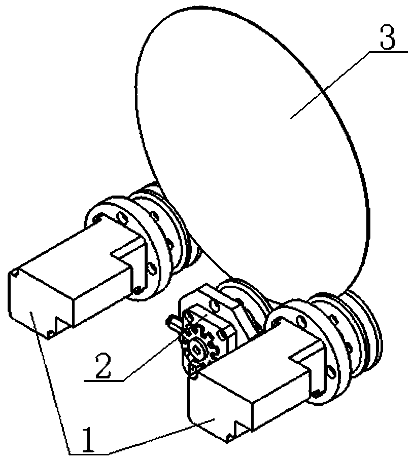
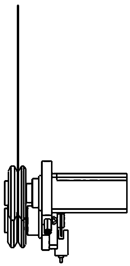
[0043] Examples see figure 1 , figure 2 As shown, the wafer combination wheel structure of this CMP post-cleaning equipment includes a drive unit 1 arranged concentrically with the center of the wafer 3, and a driven unit 2 vertically arranged concentrically with the center of the wafer 3. The coupling surfaces of the driving unit 1 and the driven unit 2 are longitudinally the same.

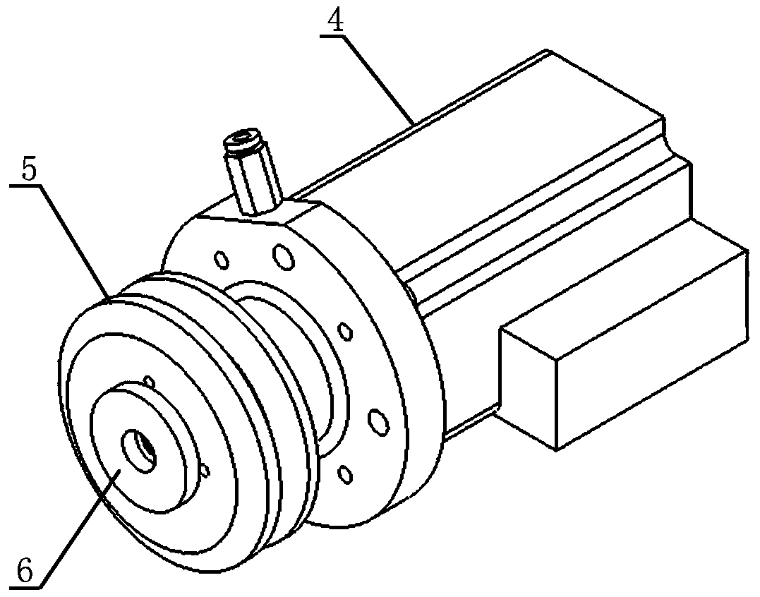
[0044] see image 3 , Figure 4 As shown, the drive unit 1 includes a drive shaft unit 4 , a drive wheel unit 5 that is socketed with the drive shaft unit 4 , and a pressure ring a6 that locks the drive wheel unit 5 to the drive shaft unit 4 .

[0045] see Figure 5 As shown, the drive shaft unit 4 includes a base a7, a drive shaft 9, a motor 10 and a through joint a11. The neck of the base a7 is covered with an O-ring a8. The motor 10 and the base a7 are fitted and fastened in the form of a hole shaft, and the through joint a11 and the base a7 are screwed and sealed in a threaded manner. ...


PUM


Abstract

The invention provides a CMP rear cleaning equipment wafer composite wheel structure and a use method. The structure comprises drive units forming a concentric circle with the center of a wafer and arranged in a leftwards-rightwards symmetrical manner and a driven unit forming a concentric circle with the center of the wafer and vertically arranged, and the wafer and the joint faces of the drive units and the driven face are longitudinally coplanar. Each drive unit comprises a drive shaft unit, a drive wheel unit in cup joint combination with the drive shaft unit and a pressing ring a for locking each drive wheel unit to the corresponding drive shaft unit. The driven unit comprises an idler shaft unit, an idler wheel unit in cup joint combination with the idler shaft unit, a pressing ring b for locking the idler wheel unit to the idler shaft unit and a sensor attached and fastened to the idler shaft unit. The drive units, the driven unit and a wafer external work environment are located in a spray agent medium. The drive units pull the wafer to perform centring rotation, the driven unit assists in bearing and clamping the wafer, and speed measurement tracking is performed along with rotation of the wafer. By means of the CMP rear cleaning equipment wafer composite wheel structure and the use method, concentric pulled rotation and online speed measurement racking can be performed on the wafer effectively and accurately.

Description

technical field [0001] The invention relates to a combined wheel structure used for dragging wafers in post-CMP cleaning equipment and a method for using the combined wheel structure. Background technique [0002] CMP (chemical mechanical Polishing) post-cleaning equipment is equipment for surface precision cleaning after high-precision polishing on the surface of electronic device wafers. In the currently available prototypes of foreign CMP post-cleaning equipment, the wafers are transported in place by an online manipulator and are separated, then slide into the combination wheel by their own weight. The friction degree on the circumference of the active rubber wheel of the existing drive unit is low, which easily causes the continuity of the concentric rotation of the supporting and rotating wafer to be unstable, that is, irregular throwing occurs, which directly affects the cleanliness of the wafer cleaning and the accuracy of speed measurement. The structure of the exi...

Claims


Application Information

Patent Timeline
Patent Type & Authority Patents(China)
IPC IPC(8): B08B13/00
CPCB08B13/00
Inventor 陶利权史霄费玖海尹影李玉敏
Owner BEIJING SEMICORE PRECISION MICROELECTRONICS EQUIP CO LTD
Why Eureka
Try Eureka